-
Welcome to the Land Rover UK Forums
You are currently viewing the site as a guest and some content may not be available to you.
Registration is quick and easy and will give you full access to the site and allow you to ask questions or make comments and join in on the conversation. If you would like to register then please Register Now
You are using an out of date browser. It may not display this or other websites correctly.
You should upgrade or use an alternative browser.
You should upgrade or use an alternative browser.
Defender Fuse Box Change
- Thread starter jeffbaker
- Start date
9
90dug
Guest
I belive devon 4x4 do them
Simon
Simon
bvudzichena
Extreme Landy Fan
You can also try Vehicle Wiring Products.
Please do a thread in Work In Progress if you were to take this project on.
I'm sure there are many forum members who would be keen to follow your example.
Please do a thread in Work In Progress if you were to take this project on.
I'm sure there are many forum members who would be keen to follow your example.
Sandy M.
Big Landy Fan
I got three 8 x way fuse holders and a pile of pre insulated connectors from Vehicle Wiring Products.
the base plate needed a little fettling to fit them in, but they all fitted OK.
I believe you might be able to get a proper Landrover conversion kit for the job - have you tried asking Porny - he is well up on these matters.
the base plate needed a little fettling to fit them in, but they all fitted OK.
I believe you might be able to get a proper Landrover conversion kit for the job - have you tried asking Porny - he is well up on these matters.
Attachments
MarcusB
Accelerating Away
I got three 8 x way fuse holders and a pile of pre insulated connectors from Vehicle Wiring Products.
the base plate needed a little fettling to fit them in, but they all fitted OK.
I believe you might be able to get a proper Landrover conversion kit for the job - have you tried asking Porny - he is well up on these matters.
I did this, and it's a very worth while upgrade.
bvudzichena
Extreme Landy Fan
Ive just changed my old fuse box to the spade type using a complete fuse box from a discovery. If youd like piccys I'll go and take some. Basicly i spliced and joined the wires coming out the back of the new box onto the wires going into the old fuse box.
H
Something tells me that wasn't a DII fuse box

Piccies would be appreciated.
Sandy M.
Big Landy Fan
I got three 8 x way fuse holders and a pile of pre insulated connectors from Vehicle Wiring Products.
I should have added that the best type of terminal to get for this job is the 6.3mm part insulated female type..
http://www.vehicle-wiring-products.eu/VWP-onlinestore/terminalspreins/photo/bf6.jpg
If you use the fully insulated type, then it will not fit into the space at the rear of the fuse box :banghead2.
I used approximately 10 of the yellow type, 6 of the red, and the rest were blue [different coloured insulation for denoting the different diameter of the cable clamps].
bvudzichena
Extreme Landy Fan
I'm not wanting to start and flame war, but I don't agree with Sandy.
I used to use crimp on connectors but found the wires come loose after a couple of years of up hill and down dale.
Now I use these and solder everything.
http://www.vehicle-wiring-products.eu/VWP-onlinestore/terminalsnonins/photo/Fb6.jpg
http://www.vehicle-wiring-products.eu/VWP-onlinestore/terminalsnonins/photo/Fbi6.jpg
SimonHobson
Extreme Landy Fan
If I might be so bold, and pedantic ...
Sandy M. and bvudzichena, you are both using the wrong type of terminals.
For a Disco fusebox I believe you should be using these Terminals. They are the last section on this page.
For most housings, such as the relay sockets used on both the defenders and Disco, you want these terminals which are "Female blade with latch" and about half way down this page.
While 'normal' unlatched sockets will often go in these housings, they may not stay in place reliably. You'll find it a real pain if you come to insert a new fuse one cold wet night in the middle of nowhere and find the terminal has pushed out the back of the fusebox At least in the original Disco fusebox there are retaining bars which offer a secondary terminal retainment.
I'd second bvudzichena's suggestion that all terminals should be soldered. I've rewired a car in the past using all crimped connections - and then suffered from the intermittent problems it's caused. It wasn't helped of course that I used one of those cheap tools (like this one) which are (IMHO) totally unsuitable for the task as they do not form a good crimp.
When I was working on my 110 a couple of years ago, I was tempted to use these fuseholders (the 16 way fuse box on this page. In the end I used their "Modular fuse and relay housing system". It took a bit of fitting, and in part I wanted to free up some space behind the panel to put the controller for the LPG system. I used a 20way fuse box, a 10way fuse + maxi relay box, and a 6way micro relay box - I was also adding relays for both main and dipped beam.
I must get out and take some piccies of it.
One problem though. I replaced the standard relay in the starter circuit with a micro relay to fit the box. Unfortunately, these seem to drop out more readily that the standard one and so I keep a straightened paper clip to hand so that when I get that "turn key, get horrible rattling" problem, I can pull the relay and stick the paper clip across the terminals
Sandy M. and bvudzichena, you are both using the wrong type of terminals.
For a Disco fusebox I believe you should be using these Terminals. They are the last section on this page.
For most housings, such as the relay sockets used on both the defenders and Disco, you want these terminals which are "Female blade with latch" and about half way down this page.
While 'normal' unlatched sockets will often go in these housings, they may not stay in place reliably. You'll find it a real pain if you come to insert a new fuse one cold wet night in the middle of nowhere and find the terminal has pushed out the back of the fusebox
At least in the original Disco fusebox there are retaining bars which offer a secondary terminal retainment.I'd second bvudzichena's suggestion that all terminals should be soldered. I've rewired a car in the past using all crimped connections - and then suffered from the intermittent problems it's caused. It wasn't helped of course that I used one of those cheap tools (like this one) which are (IMHO) totally unsuitable for the task as they do not form a good crimp.
When I was working on my 110 a couple of years ago, I was tempted to use these fuseholders (the 16 way fuse box on this page. In the end I used their "Modular fuse and relay housing system". It took a bit of fitting, and in part I wanted to free up some space behind the panel to put the controller for the LPG system. I used a 20way fuse box, a 10way fuse + maxi relay box, and a 6way micro relay box - I was also adding relays for both main and dipped beam.
I must get out and take some piccies of it.
One problem though. I replaced the standard relay in the starter circuit with a micro relay to fit the box. Unfortunately, these seem to drop out more readily that the standard one and so I keep a straightened paper clip to hand so that when I get that "turn key, get horrible rattling" problem, I can pull the relay and stick the paper clip across the terminals
I belive devon 4x4 do them
Simon
Hi any idea how much these cost from devon ?
steve@offroadin
Big Landy Fan
Sandy M.
Big Landy Fan
I'm not wanting to start and flame war, but I don't agree with Sandy.
I used to use crimp on connectors but found the wires come loose after a couple of years of up hill and down dale.
Now I use these and solder everything.
If you don't want a war, don't criticise my botching attempts
If I might be so bold, and pedantic ...
Sandy M. and bvudzichena, you are both using the wrong type of terminals.
Yer outnumbered 2 to 1, so just watch it mate
But seriously folks, I changed my fuse box as the original one was quite badly corroded, with lots of green fuzz clogging up the connections. I reckoned that since the original terminals were crimped, there was no reason why the replacements should not be crimped as well. However if your existing terminals are OK, then their may be no benefit in changing them at all.
Fair comment about crimping and soldering, that will ensure a joint with good electrical and mechanical strength.
However in my defence, when changing the terminals in situ, there was not a lot of room to work on the cable ends, and to date all the connections have remained intact.
Cheers, Sandy.
SimonHobson
Extreme Landy Fan
I reckoned that since the original terminals were crimped, there was no reason why the replacements should not be crimped as well.
But don't forget that the factory has automated equipment, carefully set up to produce good gas tight crimps. I would wager that the majority of DIY crimps (and especially most made with the cheap plier type tool) will not be properly gas tight.
By gas tight, I mean that the pressure between the mating metal faces is enough to keep gas out - ie no corrosion can happen.
However in my defence, when changing the terminals in situ, there was not a lot of room to work on the cable ends, and to date all the connections have remained intact
Yeah, it is a bit cramped to work in.
SimonHobson
Extreme Landy Fan
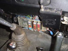
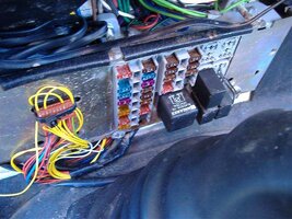
Here are a couple of pics of the box I put in my 110.
It's "not quite finished" The black and black/white wires sticking out of a relay holder are for the brake warning light test relay - I ran out of the correct terminals because there is an error on one of VWPs pages saying what terminals the relays use. The bunch of small (mostly) yellow wires to the left are for the gas conversion - I haven't made the module yet to convert the level senders for the multiple tanks to drive the dashboard gauge.
The flasher unit is in the gap behind the right hand side of the panel. The LPG ECU is behind the left side of the panel.
The large relay in the middle is for the ignition switched loads. The smaller relays in the right hand panel are for headlights (main and dipped) and starter. The top two relay spaces are currently spare, but are earmarked for extra lights. The large red cable that comes over the top of the panel and disappears through the bulkhead is an extra feed for stuff fed from this box - taking much of the load off the original harness.
It's "not quite finished"
The black and black/white wires sticking out of a relay holder are for the brake warning light test relay - I ran out of the correct terminals because there is an error on one of VWPs pages saying what terminals the relays use. The bunch of small (mostly) yellow wires to the left are for the gas conversion - I haven't made the module yet to convert the level senders for the multiple tanks to drive the dashboard gauge.The flasher unit is in the gap behind the right hand side of the panel. The LPG ECU is behind the left side of the panel.
The large relay in the middle is for the ignition switched loads. The smaller relays in the right hand panel are for headlights (main and dipped) and starter. The top two relay spaces are currently spare, but are earmarked for extra lights. The large red cable that comes over the top of the panel and disappears through the bulkhead is an extra feed for stuff fed from this box - taking much of the load off the original harness.
Attachments
HPLP
Trekker
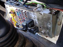
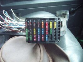
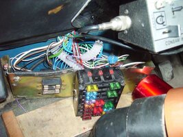
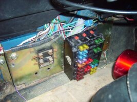
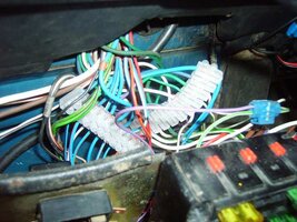
Sorry all for not putting these up sooner.
Here are the photos of what I did. Cost me very little and could easily be added to for aux stuff. Its just an old fusebox from a 1993 disco spliced into my loom using those screw in box things.
Here are the photos of what I did. Cost me very little and could easily be added to for aux stuff. Its just an old fusebox from a 1993 disco spliced into my loom using those screw in box things.
Attachments
bvudzichena
Extreme Landy Fan
That's smart.
Good job.
Fancy writing an article about it to post in our articles section?
Good job.
Fancy writing an article about it to post in our articles section?
series2a-jon
First Gear
ooh, dont like those screw connectors, theyre a fault waiting to happen, i'd have stripped soldered and heat shrinked the cables together, at least you know if you get something wrong you know where to look thoughSorry all for not putting these up sooner.
Here are the photos of what I did. Cost me very little and could easily be added to for aux stuff. Its just an old fusebox from a 1993 disco spliced into my loom using those screw in box things.