Because of the forum's limit on the length of a single post this is a continuation from Part 2 of my GM 5L40-E transmission teardown post. Clearly parts 1 & 2 need to be read first for what follows to make any sense.....
I've been reminded that I hadn't finished off this post on the 5L40-E teardown, so here goes with Part 3 of 4. Picking up from where I left off here : https://www.lrukforums.com/showthread.php/217023-GM-5L40-E-teardown-Part-2, starting with the disassembly of the main hydraulic block.....
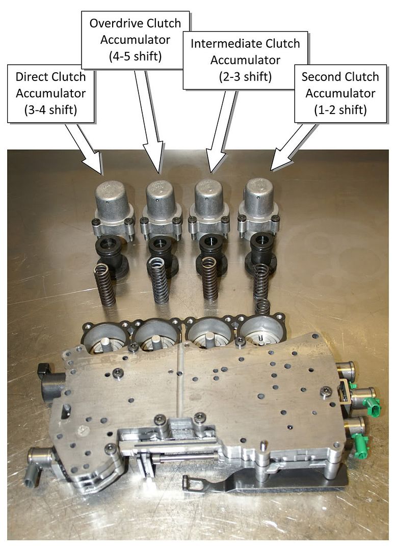
Working from the top side, the four accumulators are removed first. The accumulators are used as 'shock absorbers' to control the feel of each upshift - each of the four upshifts having its own accumulator for the oncoming clutch :
2nd clutch accumulator = 1-2 upshift
Intermediate clutch accumulator = 2-3 upshift
Direct clutch accumulator = 3-4 upshift
Overdrive clutch accumulator = 4-5 upshift
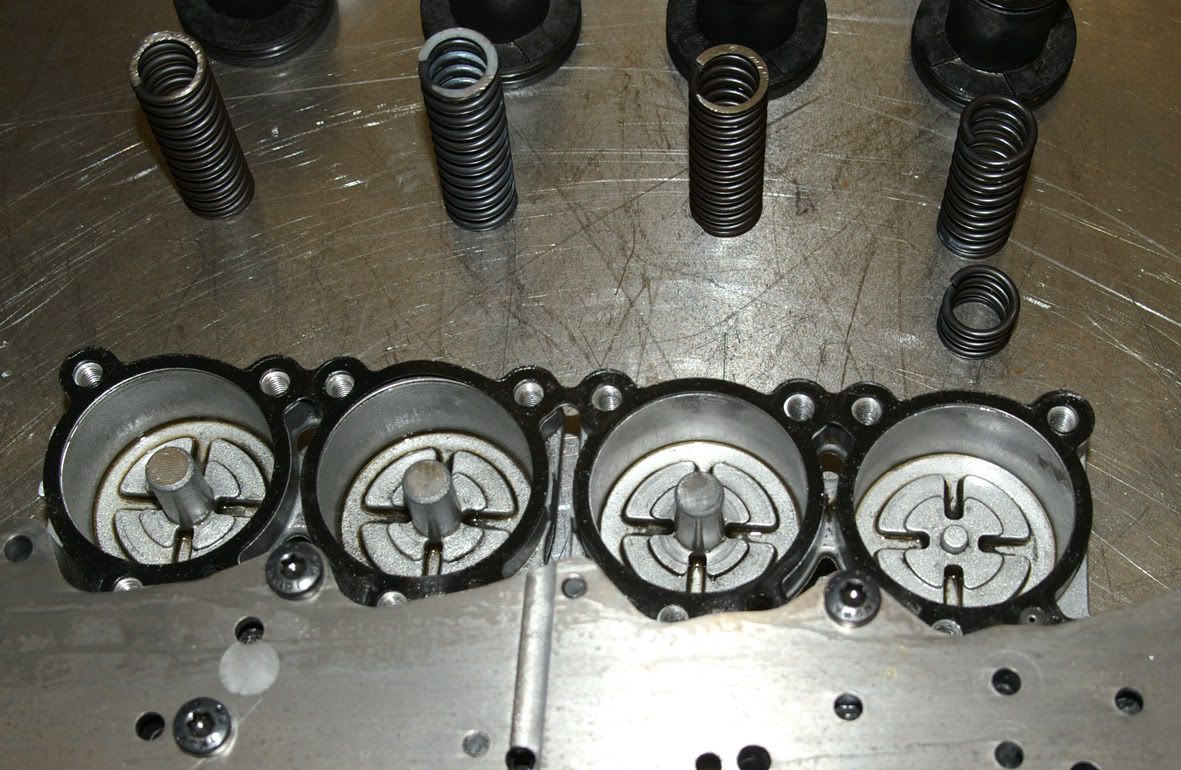
Each is made up of a housing, piston & spring. The ATSG manual states that all four accumulators are identical but this is clearly not the case for the L322 version of the 5L40-E. Three of the housings/pistons are identical (overdrive, intermediate and 2nd clutch) but the direct clutch accumulator has a larger diameter upper piston & therefore housing. The springs aren't all the same either. The overdrive & 2nd clutch accumulator springs are both identical but are longer (65mm measured free length) than the direct & intermediate clutch accumulator springs (60mm measured free length) which, again, appear to be both identical.
The photos show that the 2nd clutch accumulator spring was broken in my transmission, which must have affected the quality of the 1-2 upshift (I believe that this is quite a common complaint).
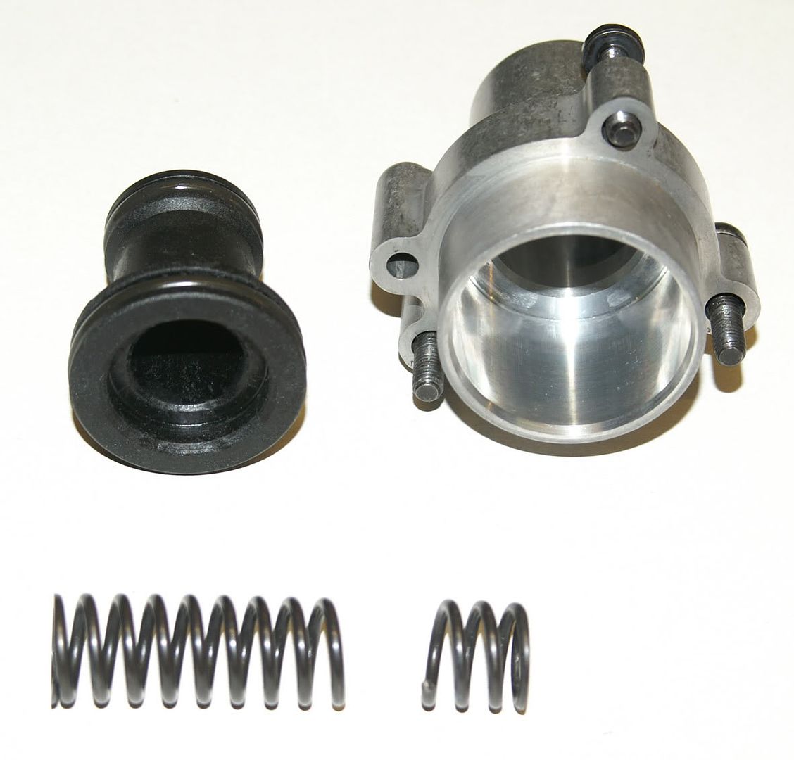
Interestingly this is the only spring of the four which doesn't have a central support cast into the valve block
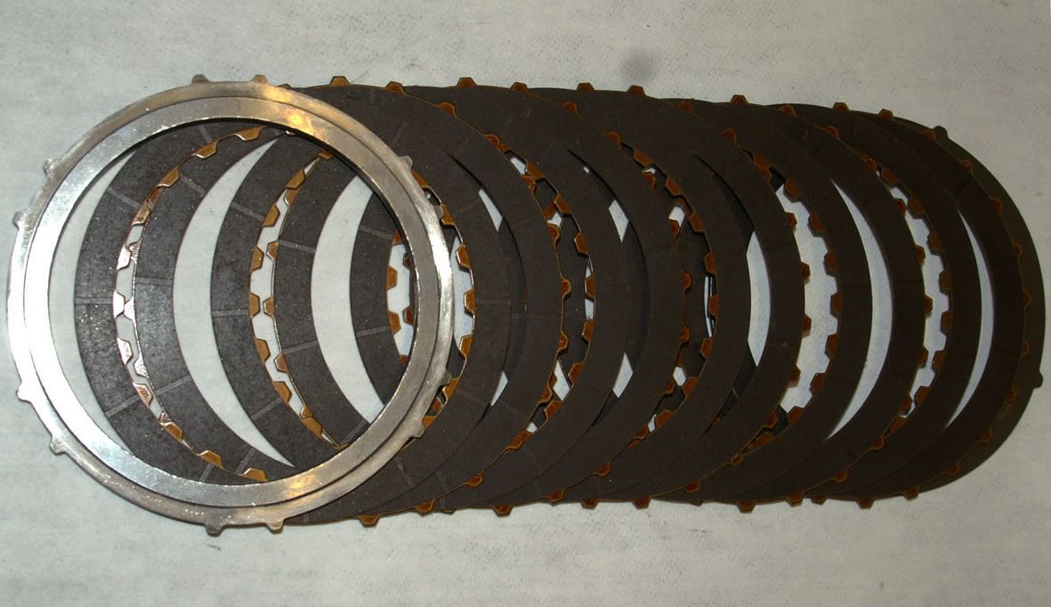
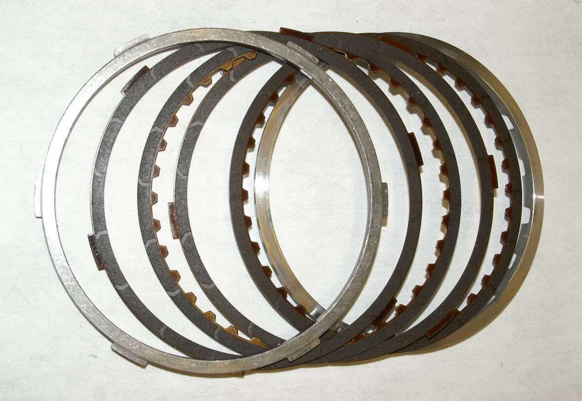
This particular transmission has the larger diameter second & second coast clutches used in the later models of the 5L40-E :
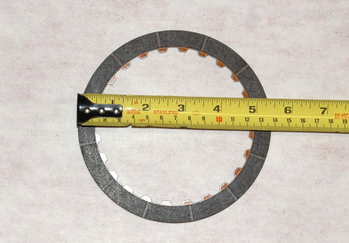
2nd clutch plate outside diameter increased from 130mm in the early models to 138mm
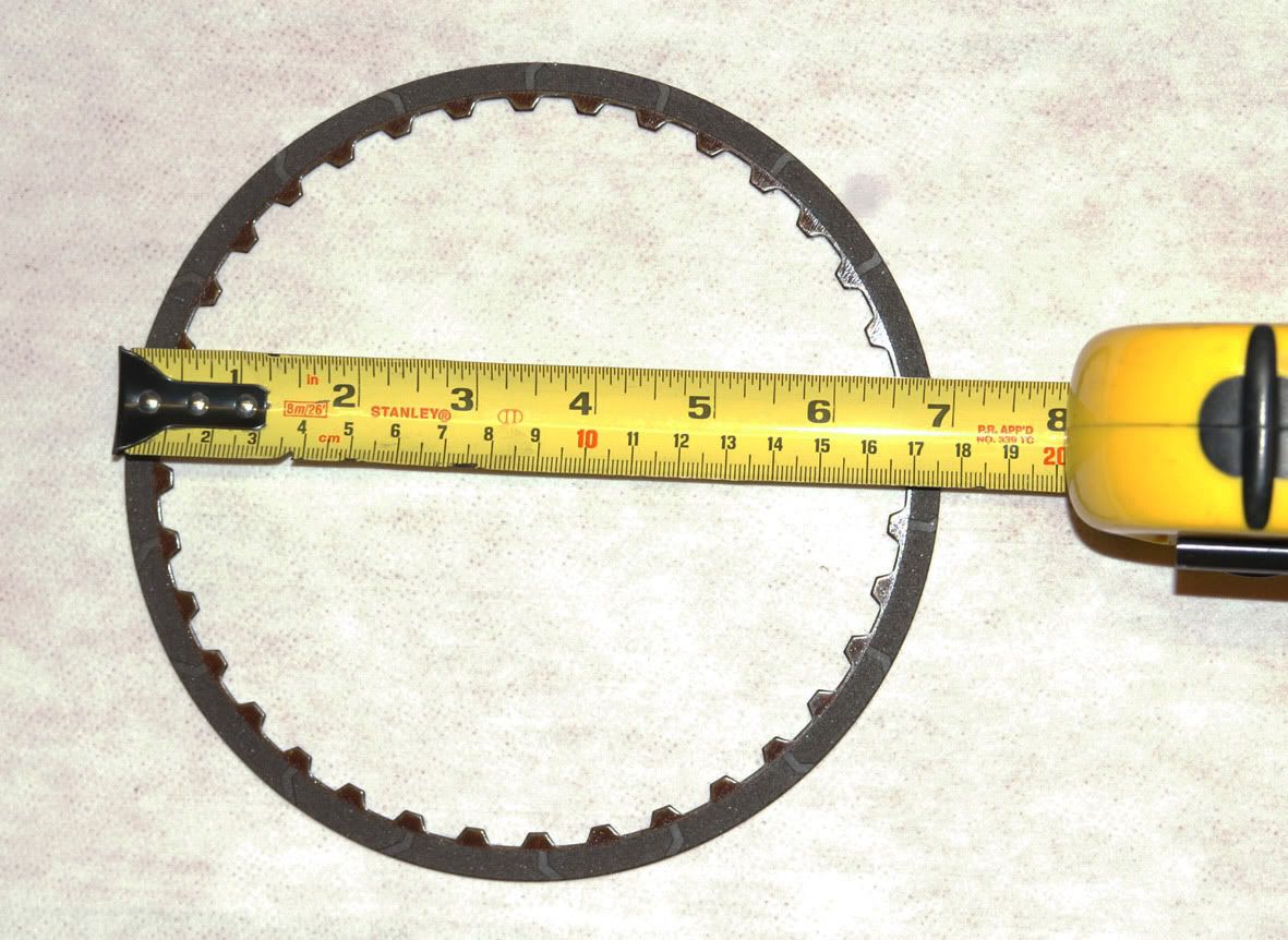
2nd coast clutch plate outside diameter increased from 173mm in the early models to 176mm
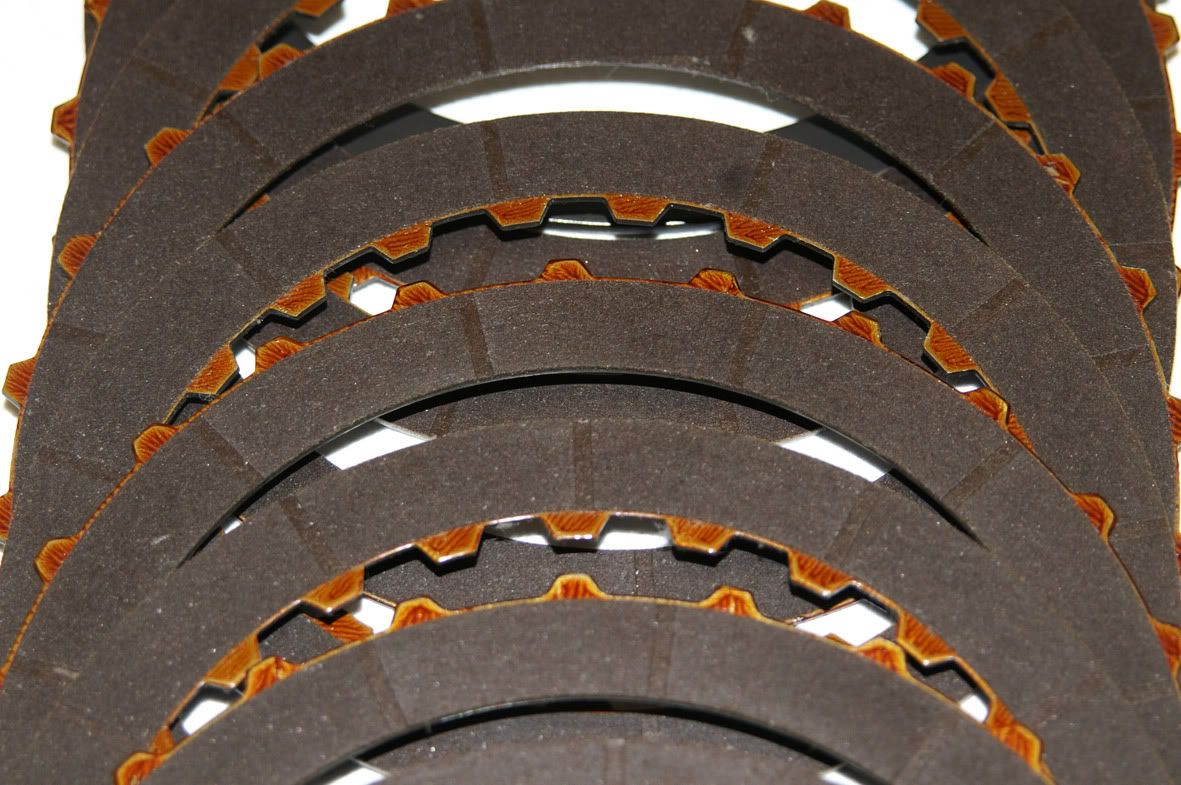
Anyway, the second & second coast clutches were in fine condition :
Back to the valve block, the seven Torx T30 headed screws are removed from the top channel plate
Followed by the remaining three screws (2 x Torx T30 and 1-off 10mm A/F, which bolts down the detent spring on the rear valve body) on the control valve body side
Both the control valve bodies can then be lifted away from the channel plates
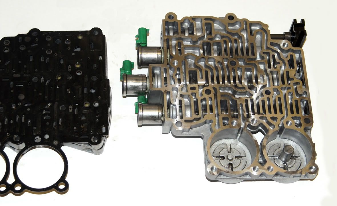
exposing the gasket which seals the control valve bodies to the spacer plate.
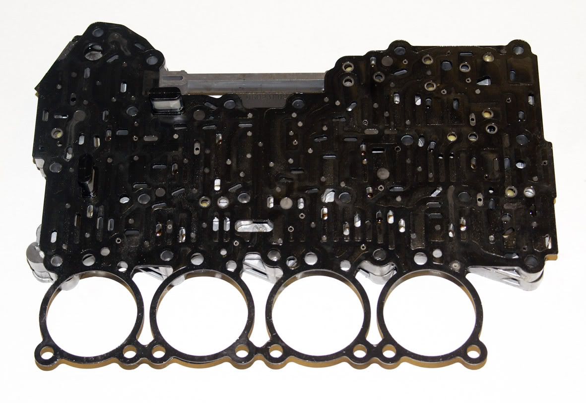
This gasket is fitted with two screens or filters. One screen is situated between the feed limit valve and the main pressure control solenoid and the other between the feed limit valve and the torque converter lock-up clutch solenoid (the feed limit valve 'caps' the pressure seen by the solenoids to prevent them being overloaded).
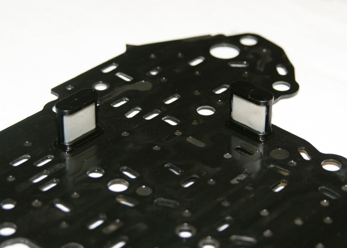
Considering the amount of metallic debris that I found in the fluid these filters are amazingly clean.
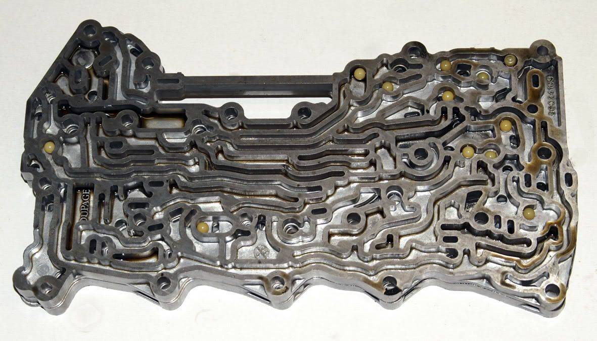
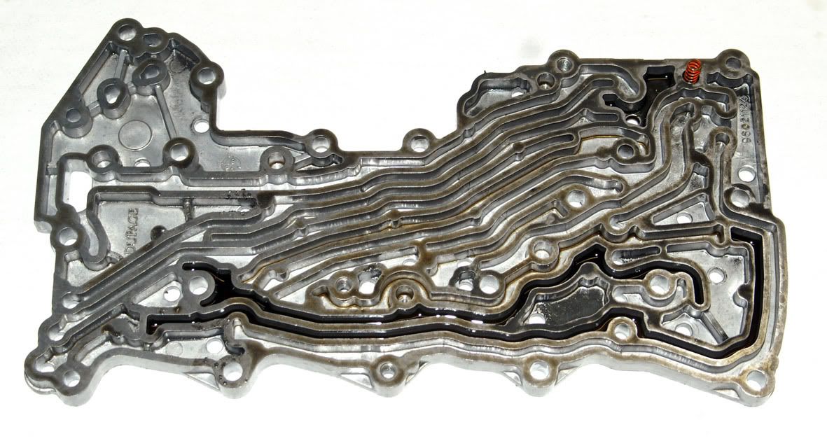
Once the spacer plate & gasket are removed the bottom channel plate can be seen with its twelve ball valves. Everything still looking okay so far........
The top & bottom channel plates can then be separated (yet another gasket)
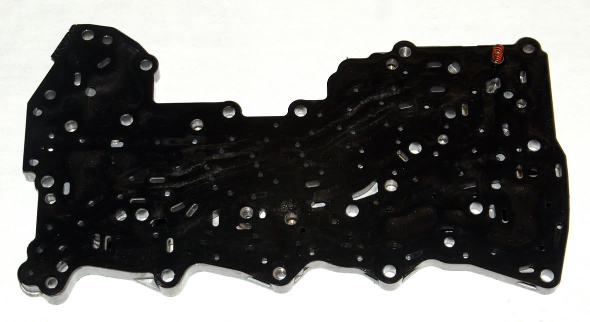
Removing the gasket leaves just the top channel plate
On the top side of the gasket an amount of metallic debris has accumulated
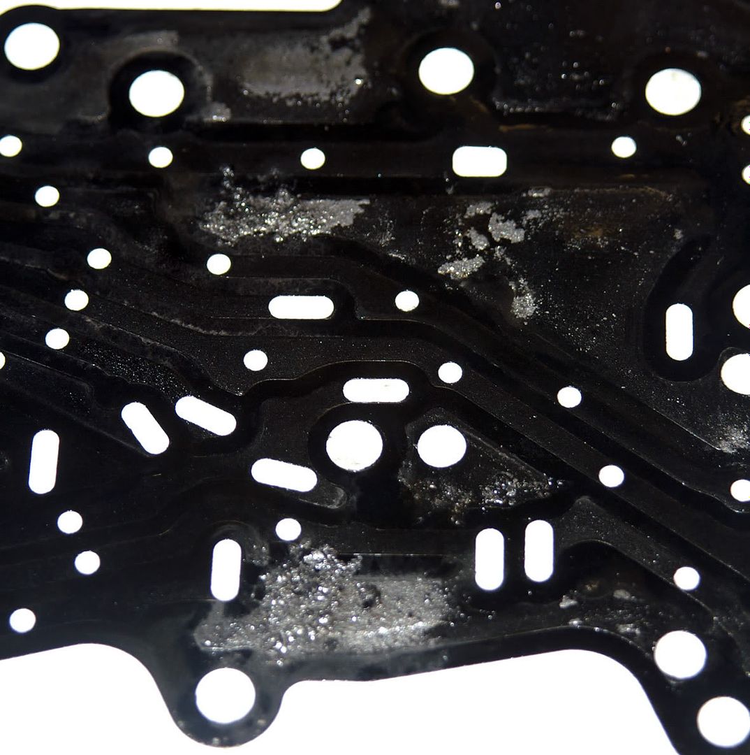
So, still nothing much yet to explain the failure.
Part 4 of this thread follows as a separate post due to the forum's limit on the length of a single post ..........
I've been reminded that I hadn't finished off this post on the 5L40-E teardown, so here goes with Part 3 of 4. Picking up from where I left off here : https://www.lrukforums.com/showthread.php/217023-GM-5L40-E-teardown-Part-2, starting with the disassembly of the main hydraulic block.....
Working from the top side, the four accumulators are removed first. The accumulators are used as 'shock absorbers' to control the feel of each upshift - each of the four upshifts having its own accumulator for the oncoming clutch :
2nd clutch accumulator = 1-2 upshift
Intermediate clutch accumulator = 2-3 upshift
Direct clutch accumulator = 3-4 upshift
Overdrive clutch accumulator = 4-5 upshift
Each is made up of a housing, piston & spring. The ATSG manual states that all four accumulators are identical but this is clearly not the case for the L322 version of the 5L40-E. Three of the housings/pistons are identical (overdrive, intermediate and 2nd clutch) but the direct clutch accumulator has a larger diameter upper piston & therefore housing. The springs aren't all the same either. The overdrive & 2nd clutch accumulator springs are both identical but are longer (65mm measured free length) than the direct & intermediate clutch accumulator springs (60mm measured free length) which, again, appear to be both identical.
The photos show that the 2nd clutch accumulator spring was broken in my transmission, which must have affected the quality of the 1-2 upshift (I believe that this is quite a common complaint).
Interestingly this is the only spring of the four which doesn't have a central support cast into the valve block
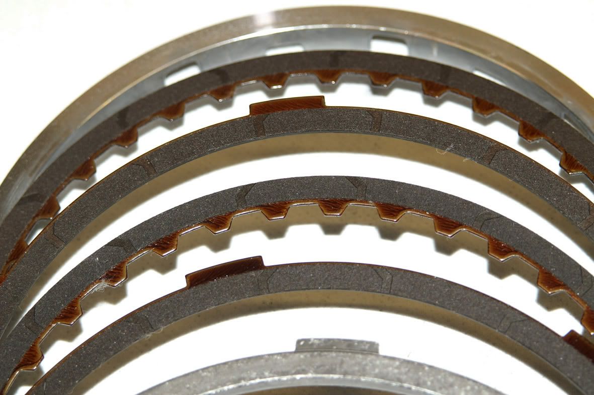
This particular transmission has the larger diameter second & second coast clutches used in the later models of the 5L40-E :
2nd clutch plate outside diameter increased from 130mm in the early models to 138mm
2nd coast clutch plate outside diameter increased from 173mm in the early models to 176mm
Anyway, the second & second coast clutches were in fine condition :
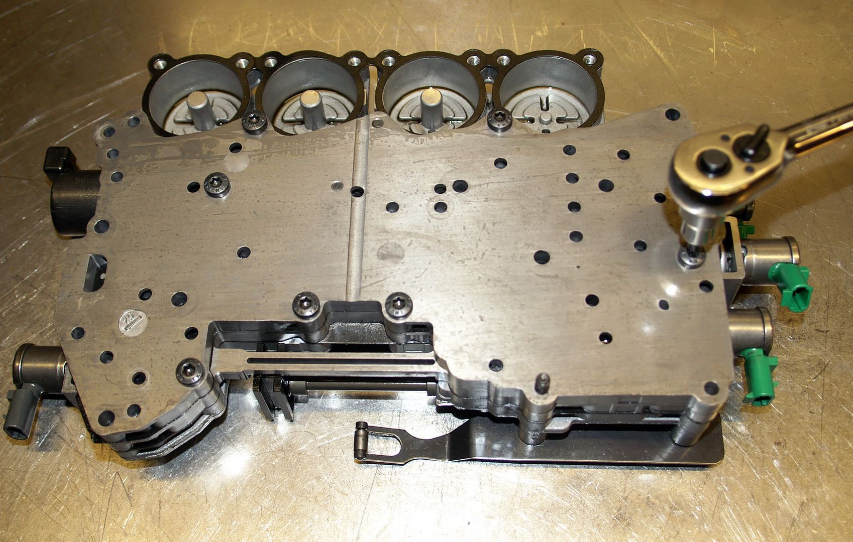
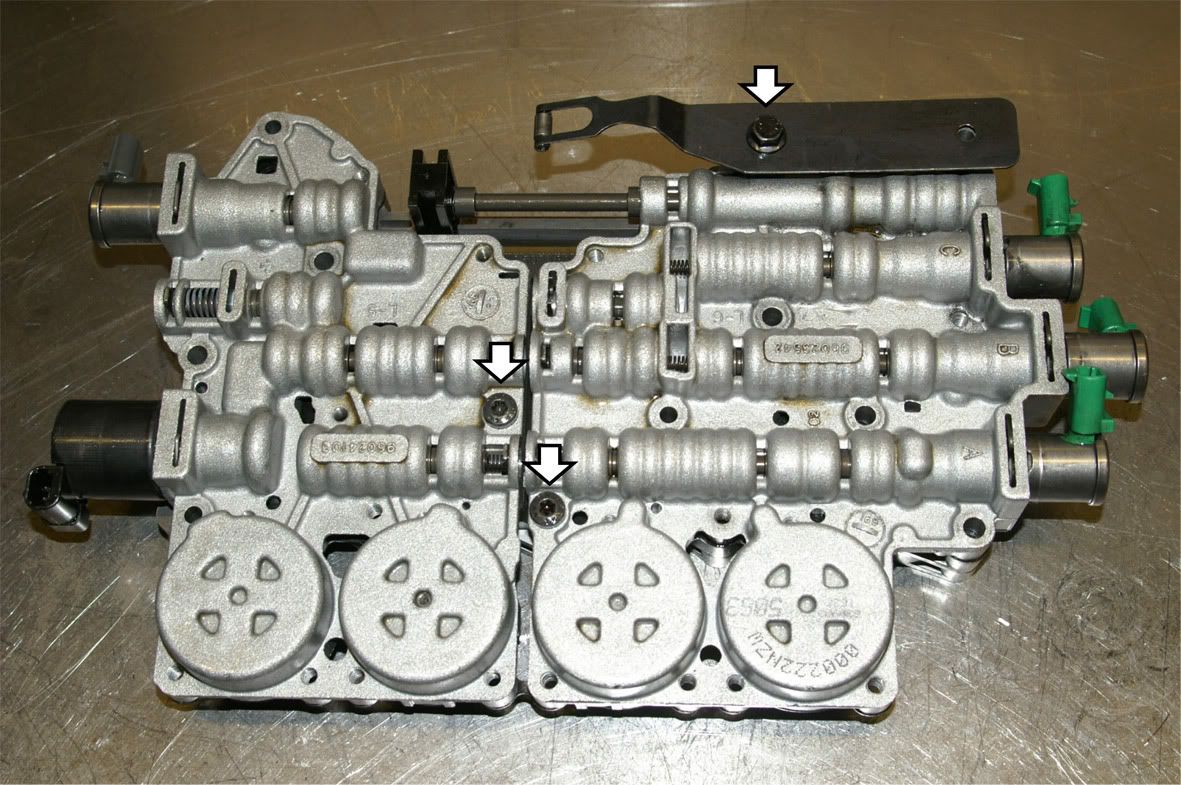
Back to the valve block, the seven Torx T30 headed screws are removed from the top channel plate
Followed by the remaining three screws (2 x Torx T30 and 1-off 10mm A/F, which bolts down the detent spring on the rear valve body) on the control valve body side
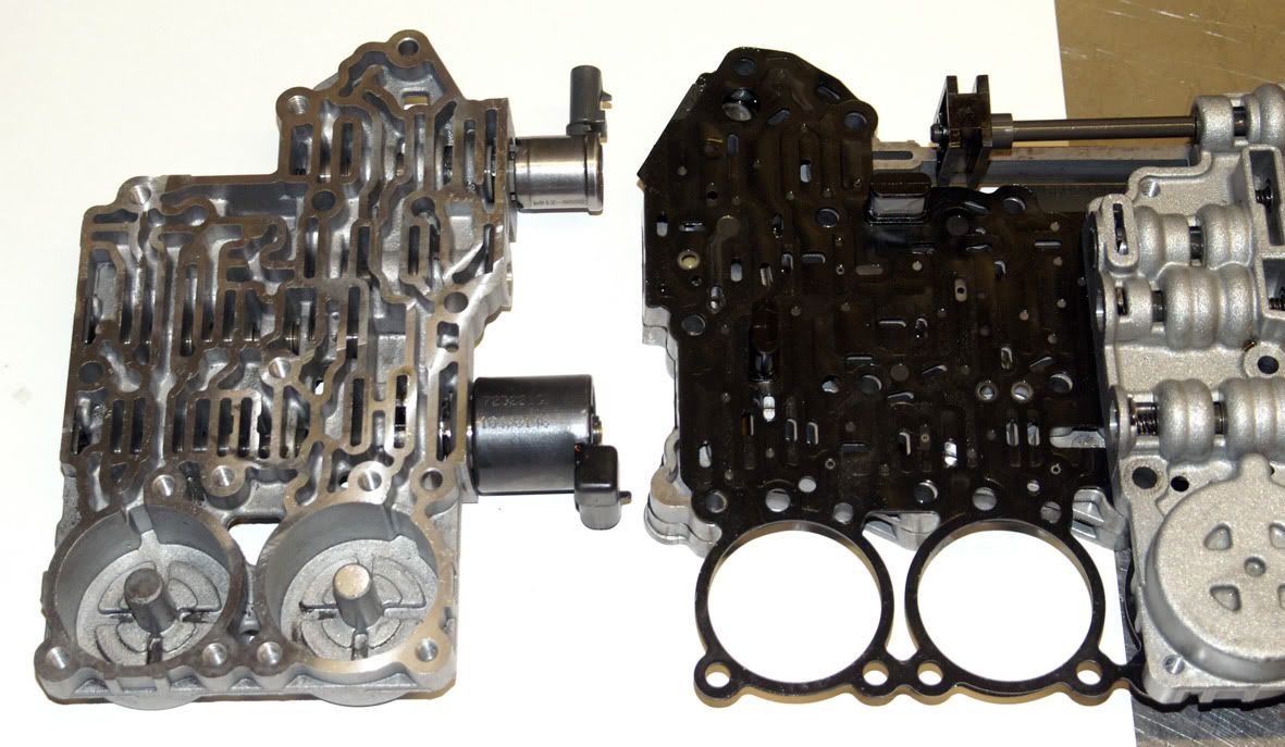
Both the control valve bodies can then be lifted away from the channel plates
exposing the gasket which seals the control valve bodies to the spacer plate.
This gasket is fitted with two screens or filters. One screen is situated between the feed limit valve and the main pressure control solenoid and the other between the feed limit valve and the torque converter lock-up clutch solenoid (the feed limit valve 'caps' the pressure seen by the solenoids to prevent them being overloaded).
Considering the amount of metallic debris that I found in the fluid these filters are amazingly clean.
Once the spacer plate & gasket are removed the bottom channel plate can be seen with its twelve ball valves. Everything still looking okay so far........
The top & bottom channel plates can then be separated (yet another gasket)
Removing the gasket leaves just the top channel plate
On the top side of the gasket an amount of metallic debris has accumulated
So, still nothing much yet to explain the failure.
Part 4 of this thread follows as a separate post due to the forum's limit on the length of a single post ..........
Last edited by a moderator: