John_P
Overdrive!
Why you may ask.
9am following day parts arrived well packaged up big thumbs up for service will use them again.
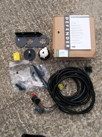
What do I get in the Kit
See attachment 01 STC 50324 Kit.jpg
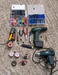
See attachment 02 Tools.jpg
Use the correct cable size (or larger don't go overboard be sensible) for the job.
Fuses are always good but useless if the correct size isn't fitted.
Don't be tempted to use scotch locks ever! they break the insulation and let the damp in the wire corrodes over time and you get a bad connection.
Use a soldered joint rather than a inline crimp connector, it's stronger, won't pull apart and wont degrade over time. It will also be smaller and if insulated with heat shrink tube or amalgam tape will be water tight (within reason).
Same applies for inline devices like fuse holders if it won't need to be removed don't use a spade or bullet connector just solder it and insulate properly if it ever need replacing just cut it out and solder in another.
If possible solder crimped on terminals after fitting it will help prevent joint degradation.
Properly prepared soldered joints always take longer but always last longer and are more reliable.
Planning
Before I started I laid the harness along the side of the car and reckoned I could make it fit without to much hassle.
The harness is really designed for under seat mounted battery of the defenders but then my disco is shorter than a 110 and with creative routing I could make it fit.
I decided I would mount the relays under the bonnet you could mount them under the chubby box and just extend the 2 wires to the battery this is how I would do it if I was to do it again.
Because I opted to mount on the RHS wing in the engine bay I needed to modify the harness
On with the Job
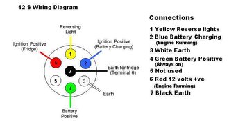
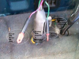
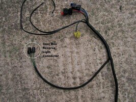
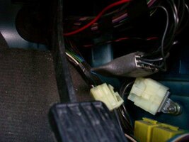
The defender 12S harness uses the plug and socket (See attachment 03 Mod connectors.jpg) to splice into the reverse light circuit at the gearbox switch (it is used as a ignition switched supply to operate the relays only when the ignition key is turned it does not use the switching function in any way) this is the same connector the disco 1 has so if you mounted the relays under the chubby box the harness would reach the switch without modification you then would only need to extend and route the 2 battery connections it would also increase the amount of harness you have to play with under the vehicle.
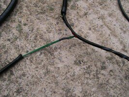
See attachment 04 remove insulation.jpg
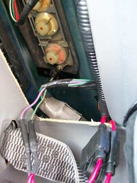
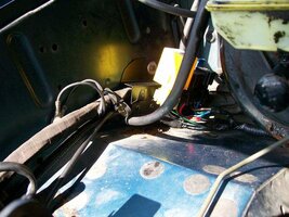
I removed the insulation tape and cut of the connection to the reverse light switch as I intend to pick up an ignition feed from terminal #1 on the fascia fuse board.
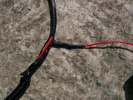
See attachment 05 solder on new wires.jpg
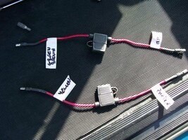
I soldered on a length or red wire insulated with 2 layers of heat shrink tubing, extended the battery +ve wire by approximately 30cm (soldered and heat shrink tubing) and re taped up the harness. I used the piece of flexy conduit removed from the reverse light connectors to protect the extended battery +ve
See attachment 06 mod complete.jpg
Disconnect the battery (ignition on pos 11 off disconnect battery within 15 seconds or to hell with it and stuff the siren with rags until the battery dies )
)
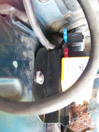
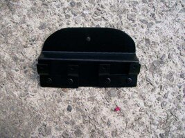
I made a mounting bracket for the relay mountings but you could just drill, paint hole with touch up paint to prevent corrosion and rivet to the wing.
See attachment 07 relay bracket.jpg
I use a rivnut and secured the bracket to the wing in an existing hole and clipped on the relays.
See attachment 08 bracket in place 01.jpg and 09 bracket in place 01.jpg
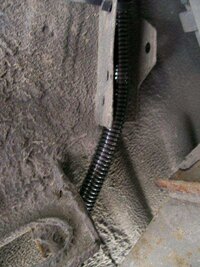
I tried to pass the red wire into the main Vehicle harness through the bulkhead and into the foot well but gave up and pierced a hole through the grommet and passed the wire through
See attachment 10 wire routing.jpg
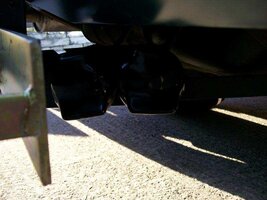
Foot well side trim panel is removed for better access you could mount the relays here above the other relays using OEM part AMR5697 relay bracket £1.80 + VAT it would gain you another 10-15cm in harness length but require passing a larger bunch of wires back through the bulkhead
Securing the wire to the existing harness and up to the fuse boards.
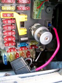
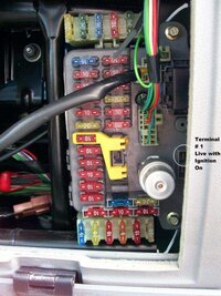
See attachment 11 fascia fuse board.jpg
Terminal #1 is switched live when the ignition is turned ON so this is the connection we want.
See attachment 12 ignition feed.jpg
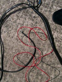
Inline fuse is added 5amp fuse and a spade terminal crimped and soldered and heat shrinked.
See attachment 13 Harness 01, 02 and 03.jpg
I tie wrapped the harness to the existing brackets (used for brake pipes on some models)
and to the top of the outrigger passing a tie through a hole round the harness and back through the hole.
The harness then followed the top of the chassis passed the sediment unit and splits yellow and green across the rear cross member with the existing 12N harness and rear light harness and up into the boot.
- http://www.mailorder4x4.com/acatalog/Christmas_Special_Offers_.html had them on offer at 37.50 +VAT retail is 155.50 + VAT
- Have needed one for the last 10 years have been running from a cobbled together socket wired to a cigarette lighter plug running through the centre of the vehicle
9am following day parts arrived well packaged up big thumbs up for service will use them again.
What do I get in the Kit
See attachment 01 STC 50324 Kit.jpg
- Mounting Bracket
- Voltage sensing Relay
- Rubber Seal
- 12S Socket
- Bag of nuts, bolts, rivets and relay mounting brackets.
- Bag of tie wraps and heat shrink tubing
- 2 Fused Relays
- Harness
- Box and instructions for defender
See attachment 02 Tools.jpg
- Heat shrink tubing (optional but preferred)
- Fuses 2 * 5amp 1 * 10 amp.
- 2 * bullet connectors 3 * spade connectors. and Crimping tool
- Soldering Iron and solder
- Screwdrivers (small and large)
- Side cutters, pliers
- Touch up paint
- Drill and bits 3mm 5mm.
- Some short lengths of cable
- 3 * inline fuse holders
- Heat Gun
- Insulation tape
- Knife
- Rivet Gun
- Multimeter.
Use the correct cable size (or larger don't go overboard be sensible) for the job.
Fuses are always good but useless if the correct size isn't fitted.
Don't be tempted to use scotch locks ever! they break the insulation and let the damp in the wire corrodes over time and you get a bad connection.
Use a soldered joint rather than a inline crimp connector, it's stronger, won't pull apart and wont degrade over time. It will also be smaller and if insulated with heat shrink tube or amalgam tape will be water tight (within reason).
Same applies for inline devices like fuse holders if it won't need to be removed don't use a spade or bullet connector just solder it and insulate properly if it ever need replacing just cut it out and solder in another.
If possible solder crimped on terminals after fitting it will help prevent joint degradation.
Properly prepared soldered joints always take longer but always last longer and are more reliable.
Planning
Before I started I laid the harness along the side of the car and reckoned I could make it fit without to much hassle.
The harness is really designed for under seat mounted battery of the defenders but then my disco is shorter than a 110 and with creative routing I could make it fit.
I decided I would mount the relays under the bonnet you could mount them under the chubby box and just extend the 2 wires to the battery this is how I would do it if I was to do it again.
Because I opted to mount on the RHS wing in the engine bay I needed to modify the harness
On with the Job
The defender 12S harness uses the plug and socket (See attachment 03 Mod connectors.jpg) to splice into the reverse light circuit at the gearbox switch (it is used as a ignition switched supply to operate the relays only when the ignition key is turned it does not use the switching function in any way) this is the same connector the disco 1 has so if you mounted the relays under the chubby box the harness would reach the switch without modification you then would only need to extend and route the 2 battery connections it would also increase the amount of harness you have to play with under the vehicle.
See attachment 04 remove insulation.jpg
I removed the insulation tape and cut of the connection to the reverse light switch as I intend to pick up an ignition feed from terminal #1 on the fascia fuse board.
See attachment 05 solder on new wires.jpg
I soldered on a length or red wire insulated with 2 layers of heat shrink tubing, extended the battery +ve wire by approximately 30cm (soldered and heat shrink tubing) and re taped up the harness. I used the piece of flexy conduit removed from the reverse light connectors to protect the extended battery +ve
See attachment 06 mod complete.jpg
Disconnect the battery (ignition on pos 11 off disconnect battery within 15 seconds or to hell with it and stuff the siren with rags until the battery dies
)I made a mounting bracket for the relay mountings but you could just drill, paint hole with touch up paint to prevent corrosion and rivet to the wing.
See attachment 07 relay bracket.jpg
I use a rivnut and secured the bracket to the wing in an existing hole and clipped on the relays.
See attachment 08 bracket in place 01.jpg and 09 bracket in place 01.jpg
I tried to pass the red wire into the main Vehicle harness through the bulkhead and into the foot well but gave up and pierced a hole through the grommet and passed the wire through
See attachment 10 wire routing.jpg
Foot well side trim panel is removed for better access you could mount the relays here above the other relays using OEM part AMR5697 relay bracket £1.80 + VAT it would gain you another 10-15cm in harness length but require passing a larger bunch of wires back through the bulkhead
Securing the wire to the existing harness and up to the fuse boards.
See attachment 11 fascia fuse board.jpg
Terminal #1 is switched live when the ignition is turned ON so this is the connection we want.
See attachment 12 ignition feed.jpg
Inline fuse is added 5amp fuse and a spade terminal crimped and soldered and heat shrinked.
See attachment 13 Harness 01, 02 and 03.jpg
I tie wrapped the harness to the existing brackets (used for brake pipes on some models)
and to the top of the outrigger passing a tie through a hole round the harness and back through the hole.
The harness then followed the top of the chassis passed the sediment unit and splits yellow and green across the rear cross member with the existing 12N harness and rear light harness and up into the boot.
Attachments
-
 01 STC 50324 Kit.jpg88.1 KB · Views: 271
 -
 02 Tools.jpg99.7 KB · Views: 146
 -
 03 Mod Connectors.jpg89.4 KB · Views: 224
 -
 08 bracket in place 1.jpg46 KB · Views: 155
 -
 07 Relay Bracket.jpg87.8 KB · Views: 121
 -
 06 Mod complete.jpg105 KB · Views: 157
 -
 05 Solder on new Wire.jpg99.4 KB · Views: 146
 -
 04 Remove Insulation.jpg96.2 KB · Views: 146
 -
 13 Harness 01.jpg56.8 KB · Views: 144
 -
 12 Ignition feed.jpg53.7 KB · Views: 195
 -
 11 Facia Fuse board.jpg61 KB · Views: 218
 -
 10 wire routing.jpg34.2 KB · Views: 188
 -
 09 Bracket in place 2.jpg58.4 KB · Views: 152
 -
 13 Harness 02.jpg69.9 KB · Views: 148
 -
 13 Harness 03.jpg34.7 KB · Views: 149