i'm just in awe of how much into this your are willing to go..steady on now fella, offering me your body!
-
Welcome to the Land Rover UK Forums
You are currently viewing the site as a guest and some content may not be available to you.
Registration is quick and easy and will give you full access to the site and allow you to ask questions or make comments and join in on the conversation. If you would like to register then please Register Now
You are using an out of date browser. It may not display this or other websites correctly.
You should upgrade or use an alternative browser.
You should upgrade or use an alternative browser.
Cliff's Disco 2 thread
- Thread starter Cliff4WD
- Start date
I'm emotionally attached. I'm wondering just how far I can actually manage, I still have the right hand side to look at yet and I doubt it will that much different (looks less far gone from the outside). Trouble is there's slight issue of steering column, brake and clutch pedals, fusebox, instrument pod, etc. It's the thought of all that that has stopped me removing the entire dash already even though it would be a lot easier to access and work on with it out of the way.i'm just in awe of how much into this your are willing to go..
Thanks for the support, it does help to keep me going.
I've been playing with video again...
I enjoyed that well put together video….I've been playing with video again...
It's a real balls ache not having an indoor space to work. I've had rain, snow, and gale force winds since my last posts, and so no more work done as a consequence. Add to that my chronic health issues and progress is very sloooow. Still, no real rush is there.
After having removed the strengthening panel and getting a better look at what was lurking underneath, I decided that the best course of action was to remove the rest of the corroded steel and reveal the body mounting bracket.

The bracket itself is in good order and is solid. It looks a bit grubby with some surface rust, but it's fine. I decided to leave the body mounting bolt in place so that I didn't run into problems losing alignment. There's still part of it welded to the bulkhead inside the engine bay out of harms way, so it's not going anywhere. I carried on cutting and cleaning.

Having settled on what I was removing and what was staying and having done the cutting and a bit of grinding, it was time for a wire brush and some rust treatment.

Next phase of the repair was to make a new template to fit the hole. I decided to start afresh even though I'd already fabricated a new repair panel as I want to ensure I make a good strong repair. I may make use of the panel I made previously as a strengthener; we'll see. Today's task was then to cut a new template.
It all sounds so straight forward, but twisting and contorting, back and forth, adjusting, measuring, trial fitting, etc., and most of the day seems to disappear. The result, a sad looking piece of cornflake packet.

It didn't take long to transfer this shape to a sheet of steel and cut it out.

You can see from the photo that I marked out the position of the holes I need to drill for the plug welds I'll be using to attach it to the mounting bracket.
Once the holes were drilled, I set about bending the panel to shape so that it fits the space. This I could do simply hand bending it supported in my bench vice. All trial and error but not too difficult. I work out the line on which the bend takes place and gently bend around it checking for fit as I go.

The hardest part of this was working under the dash and trying to match up to the loom grommet opening. It would definitely be a whole lot easier to access with the entire dash assembly out of the way (something I may yet have to do when I get to the off-side repairs).
I was quite happy with the fit I managed to achieve as it should all weld up nicely.


Left it there for today. Next job will be to get some primer on and get it welded up.
After having removed the strengthening panel and getting a better look at what was lurking underneath, I decided that the best course of action was to remove the rest of the corroded steel and reveal the body mounting bracket.
The bracket itself is in good order and is solid. It looks a bit grubby with some surface rust, but it's fine. I decided to leave the body mounting bolt in place so that I didn't run into problems losing alignment. There's still part of it welded to the bulkhead inside the engine bay out of harms way, so it's not going anywhere. I carried on cutting and cleaning.
Having settled on what I was removing and what was staying and having done the cutting and a bit of grinding, it was time for a wire brush and some rust treatment.
Next phase of the repair was to make a new template to fit the hole. I decided to start afresh even though I'd already fabricated a new repair panel as I want to ensure I make a good strong repair. I may make use of the panel I made previously as a strengthener; we'll see. Today's task was then to cut a new template.
It all sounds so straight forward, but twisting and contorting, back and forth, adjusting, measuring, trial fitting, etc., and most of the day seems to disappear. The result, a sad looking piece of cornflake packet.
It didn't take long to transfer this shape to a sheet of steel and cut it out.
You can see from the photo that I marked out the position of the holes I need to drill for the plug welds I'll be using to attach it to the mounting bracket.
Once the holes were drilled, I set about bending the panel to shape so that it fits the space. This I could do simply hand bending it supported in my bench vice. All trial and error but not too difficult. I work out the line on which the bend takes place and gently bend around it checking for fit as I go.
The hardest part of this was working under the dash and trying to match up to the loom grommet opening. It would definitely be a whole lot easier to access with the entire dash assembly out of the way (something I may yet have to do when I get to the off-side repairs).
I was quite happy with the fit I managed to achieve as it should all weld up nicely.
Left it there for today. Next job will be to get some primer on and get it welded up.
Well done mate. Especially with the weather to contend with.
Slapped on a few coats of Galvafroid today ready for the weldup.

I keep having to deal with everything else under the sun other than getting on and finishing this phase of my repairs. Today I thought I'd position my new zinc primed panel in position ready for welding. I'd left a few odd areas around the periphery of the hole to trim and also needed to get the panel sitting tight to the mounting bracket and to all edges and surfaces. I also wanted to get the gaps as tight as I could manage.


It looks about right but did take a bit of persuading.
I've been meaning to buy myself a set of those Clico rivet clamp things, but had to rely on a few self tapping screws to pull it all together

A few more gaps than I intended but basically where it needs to be. I managed to get the overlap under the floor up tight too. I'm undecided whether to plug this edge and seam or just seam weld it.

Probably I'll make a few more minor adjustments before I get welding, but it's pretty much ready to go.
In the meantime, remember I mentioned bending the forcing screw on my nice new never been used before expensive ball joint removal G clamp tool? Well, I managed to get it replaced with a nice new one. I just hope I don't manage to bend this one.
While I had the Galvafroid out yesterday, I slapped a couple of coats on the axle end ready for it's new ball joints.

That's it for today
It looks about right but did take a bit of persuading.
I've been meaning to buy myself a set of those Clico rivet clamp things, but had to rely on a few self tapping screws to pull it all together
A few more gaps than I intended but basically where it needs to be. I managed to get the overlap under the floor up tight too. I'm undecided whether to plug this edge and seam or just seam weld it.
Probably I'll make a few more minor adjustments before I get welding, but it's pretty much ready to go.
In the meantime, remember I mentioned bending the forcing screw on my nice new never been used before expensive ball joint removal G clamp tool? Well, I managed to get it replaced with a nice new one. I just hope I don't manage to bend this one.
While I had the Galvafroid out yesterday, I slapped a couple of coats on the axle end ready for it's new ball joints.
That's it for today
Tom Mepham
Big Landy Fan
Looking good cliff, those ball joints are hard work!
I managed to use a hydraulic puller set to press the new ball joints in on ours last year. Bit of a fiddle but it worked.
I used genuine LR joints again as the originals had done 200,000miles, I don’t want to be doing it again any time soon! I also did new CV gators and NAK shaft seals in the ends of the axle tube, cleaned and painted then finished with Dinitrol
Attachments
Nice job Tom. I have an hydraulic bearing puller which I was thinking I might try to use for this if I have any more trouble. It's a shame I had to put so much force on the joints to break the taper as they were still good; just perished rubber boots. I had hoped to get away with just replacing the covers but no joy, anyway, while there it's one of those things not worth skimping on. I just didn't bargain for the amount of rot I found in the arch. I have a pair of NAK seals for the shafts, and cv boots, so will be doing same as youm, plus the ARB drop links and bushes.Looking good cliff, those ball joints are hard work!
I managed to use a hydraulic puller set to press the new ball joints in on ours last year. Bit of a fiddle but it worked.
I used genuine LR joints again as the originals had done 200,000miles, I don’t want to be doing it again any time soon! I also did new CV gators and NAK shaft seals in the ends of the axle tube, cleaned and painted then finished with Dinitrol
Today was weld her up day! Well, that was the plan at least.
I really could have thought things through a bit better before putting it on stands and taking the wheels off, mind you, to be fair I thought I was replacing the ball joints at the time. However, working through the door with a bloomin great birch tree in the way is an absolute pain Anyway, I rolled out the MIG and positioned things as close as I could manage ready to start work.


This is one of those jobs where you get so involved that you forget to stop to take photos, also I was a bit embarrassed with the welding I was achieving. The problem is access and visibility. Trying to get into the space with a welding helmet on and holding the torch at the angle you want it and not being able to see a what your'e doing while knocking the helmet off your head and the torch not fitting in the space you want it, swearing and cursing, and getting absolutely miserable because it's all starting to go pear shaped, is all a bit trying - putting it mildly.
A bit of fighting with it was involved but I did get it in position and tacked and plugged.

I was quite pleased that I at least managed to align it at the top edge so that I can get the grommet(s) refitted.


As I said, I'm not that happy with my welding so far, but when I finish it off at least I'm a dab hand with the angle grinder
At least there's light at the end of tunnel on this now. once its seam sealed and painted I should be able to forget about this particular problem. Of course, I still have the inner valance parts to fabricate and weld and a few patches in the arch, then there's the other side to properly investigate. Ooh err, maybe the light is a train coming to get me!
I really could have thought things through a bit better before putting it on stands and taking the wheels off, mind you, to be fair I thought I was replacing the ball joints at the time. However, working through the door with a bloomin great birch tree in the way is an absolute pain
Anyway, I rolled out the MIG and positioned things as close as I could manage ready to start work.This is one of those jobs where you get so involved that you forget to stop to take photos, also I was a bit embarrassed with the welding I was achieving. The problem is access and visibility. Trying to get into the space with a welding helmet on and holding the torch at the angle you want it and not being able to see a what your'e doing while knocking the helmet off your head and the torch not fitting in the space you want it,
swearing and cursing, and getting absolutely miserable because it's all starting to go pear shaped, is all a bit trying - putting it mildly.A bit of fighting with it was involved but I did get it in position and tacked and plugged.
I was quite pleased that I at least managed to align it at the top edge so that I can get the grommet(s) refitted.
As I said, I'm not that happy with my welding so far, but when I finish it off at least I'm a dab hand with the angle grinder
At least there's light at the end of tunnel on this now. once its seam sealed and painted I should be able to forget about this particular problem. Of course, I still have the inner valance parts to fabricate and weld and a few patches in the arch, then there's the other side to properly investigate. Ooh err, maybe the light is a train coming to get me!
German Grüner
Offroader
Your weldingds are brillant! I usually make weldings with angle grinder mounted with flapper disc in the other hand, haha!
Tom Mepham
Big Landy Fan
Also for this sort of work I bought an electric die grinder and some tungsten carbide burrs. You can tidy up welds in difficult places and you can grind out original spot welds in difficult places to remove panels if you are doing rust repairs. Great bit of kit. I only got a 30quid one from eBay but bought decent bits for it.
I have a set of burrs on my wish list. There's so much on it I never seem to get around to buying the things that I really need. I'm using various air tools at the moment and an electric angle grinder.Also for this sort of work I bought an electric die grinder and some tungsten carbide burrs. You can tidy up welds in difficult places and you can grind out original spot welds in difficult places to remove panels if you are doing rust repairs. Great bit of kit. I only got a 30quid one from eBay but bought decent bits for it.
Apologies for the slow pace of this repair. I've been back at it and made more progress so here's the write-up.
I finished welding the replacement panel in place and dressed the welds a bit. I know it will all be hidden under the carpet when I put it back in, but I hate seeing welded patches etc. on show. Also, I'm embarrassed by the state of some of it :red:

Welding thin gauge steel requires heat control to avoid warping and distortion, this invariably requires lots of spots of weld rather than runs and leaves the odd pin holes here and there, so a skim of filler over the welds is a good idea

After flattening this back, I apply brush on seam sealer over all seams and welded joints

outside as well as inside

Now, there's still the section of the inner arch that I cut out to deal with, so it's template time again. I used the masking tape trick this time to find the shape of the patch piece required.

I transferred this to card and used it to mark out my steel sheet.


This was then cut out and bent into the necessary shape to fit the hole


Trial fitting took a while getting it to fit just right as it's such an awkward spot to get at with the main loom in the way.


After a bit of fettling, I managed to get a reasonable fit ...

... and got welding


Next job for today was to get some primer on it


I'll do the seam sealing when the paint's dry and then underseal, etc.
I'm pretty relieved that this side is now done (I think I'll have to add some strengthening inside with a second skin) and I can get back where I started and replace the ball joints :biggrin:
I finished welding the replacement panel in place and dressed the welds a bit. I know it will all be hidden under the carpet when I put it back in, but I hate seeing welded patches etc. on show. Also, I'm embarrassed by the state of some of it :red:
Welding thin gauge steel requires heat control to avoid warping and distortion, this invariably requires lots of spots of weld rather than runs and leaves the odd pin holes here and there, so a skim of filler over the welds is a good idea
After flattening this back, I apply brush on seam sealer over all seams and welded joints
outside as well as inside
Now, there's still the section of the inner arch that I cut out to deal with, so it's template time again. I used the masking tape trick this time to find the shape of the patch piece required.
I transferred this to card and used it to mark out my steel sheet.
This was then cut out and bent into the necessary shape to fit the hole
Trial fitting took a while getting it to fit just right as it's such an awkward spot to get at with the main loom in the way.
After a bit of fettling, I managed to get a reasonable fit ...
... and got welding
Next job for today was to get some primer on it
I'll do the seam sealing when the paint's dry and then underseal, etc.
I'm pretty relieved that this side is now done (I think I'll have to add some strengthening inside with a second skin) and I can get back where I started and replace the ball joints :biggrin:
Looking good!
I wouldnt be embarrassed by that, its far better than I would be able to do!
I wouldnt be embarrassed by that, its far better than I would be able to do!
Not at all embarrassing you've done better welding than I've paid professional garages for!
Most definitely a million times better than anything I've achieved with mine. I spend more time with the grinder and filler afterwards than I do welding and it still looks way worse than yours!
Most definitely a million times better than anything I've achieved with mine. I spend more time with the grinder and filler afterwards than I do welding and it still looks way worse than yours!
A bit more progress. Happy to have got the welding out of the way (nearside) and all seams sealed and primed. Today was a coat of underseal on the new steel and touch-up the damaged areas.

So with that put to bed as it were, I can at finally get back to the ball joints :smile2: Did I mention that I managed to bend the forcing screw on my nice new expensive ball joint fitting tool? I was pleasantly surprised that Cromwell Tools were happy to refund/replace it under warranty. I opted for a replacement as I'm pretty sure I can manage to avoid doing the same again and I have no idea what quality the various versions available on ebay, etc., are like. I note that all the tools look identical and you have to wonder if they are all from the same manufacturer in China somewhere? The Kennedy version I have costs about 3 times more than the rest and does seem to be quality HT steel. Who knows, maybe I'm being a mug but it's the best I can afford at the moment - a nice sykes pickvant oem type would be cool but I'm only a diy hobbyist level user so maybe a bit OTT. I digress.
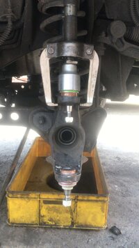
I then suffered some senior OMG is it dimentia on the way thinking as I puzzled which way was best to use the tool and which joint to do first? I opted for bottom joint first.

There's a bit of frost on the joint as I had it in the freezer overnight. It pushed into the yoke without too much problem. I did stop half way and use another receiver to allow for the joint to poke its head up through the hole.

Finally have the first new joint in place.
Next I decided to fit a new seal in the axle case end. I've had a pair of spares sat in my parts bin for ages. They were wrapped in an envelope sent to me by some fella called Tony in Braintree :wink1:

I tapped this into position using the special tool; my hub nut socket!
Time for the top joint ...

... and it's in!

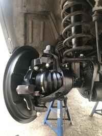
Next I thought I'd give the steering knuckle a good clean, get rid of the surface rust, and give it a paint.

A lot of work with the wire brush on the grinder and it was looking half decent

Same with the back plate

I then masked up the knuckle and gave them a coat of the zinc primer


And then it started to rain and it was beer o'clock anyway, so that's it for today.
So with that put to bed as it were, I can at finally get back to the ball joints :smile2: Did I mention that I managed to bend the forcing screw on my nice new expensive ball joint fitting tool? I was pleasantly surprised that Cromwell Tools were happy to refund/replace it under warranty. I opted for a replacement as I'm pretty sure I can manage to avoid doing the same again and I have no idea what quality the various versions available on ebay, etc., are like. I note that all the tools look identical and you have to wonder if they are all from the same manufacturer in China somewhere? The Kennedy version I have costs about 3 times more than the rest and does seem to be quality HT steel. Who knows, maybe I'm being a mug but it's the best I can afford at the moment - a nice sykes pickvant oem type would be cool but I'm only a diy hobbyist level user so maybe a bit OTT. I digress.
I then suffered some senior OMG is it dimentia on the way thinking as I puzzled which way was best to use the tool and which joint to do first? I opted for bottom joint first.
There's a bit of frost on the joint as I had it in the freezer overnight. It pushed into the yoke without too much problem. I did stop half way and use another receiver to allow for the joint to poke its head up through the hole.
Finally have the first new joint in place.
Next I decided to fit a new seal in the axle case end. I've had a pair of spares sat in my parts bin for ages. They were wrapped in an envelope sent to me by some fella called Tony in Braintree :wink1:
I tapped this into position using the special tool; my hub nut socket!
Time for the top joint ...
... and it's in!
Next I thought I'd give the steering knuckle a good clean, get rid of the surface rust, and give it a paint.
A lot of work with the wire brush on the grinder and it was looking half decent
Same with the back plate
I then masked up the knuckle and gave them a coat of the zinc primer
And then it started to rain and it was beer o'clock anyway, so that's it for today.
I'm losing the will to live; F*#$£*&# Land Rover. Why on earth we all "enthuse" about these piles of rubbish I'll never know. Today, after breaking off for the weekend for a much needed rain storm and then giving the whole vehicle a good power wash to shift the fast growing layer of pigeon droppings, I discovered that the dense foam sound insulation under the dash inside the vehicle was wringing wet. Now obviously it's not wet from the wheel arch/bulkhead valley in the engine bay that I've just repaired, so question was, where exactly is the water getting inside? this is serious as it negates everything I've just done to stop this ingress.
The obvious area to suspect is the scuttle which retains water if it cannot get out of the drain holes (and it never will unless parked at least slightly downhill). I'm compromised at the moment what with the vehicle being up on stands at the front (why are there no drain holes at the rear as well as the from of the scuttle tray? - I think I'll be drilling some!).
A visual inspection of the scuttle and at my previous repairs there didn't reveal anything obvious. Since I have the cover plate off of the bulkhead, I can get my hands in and underneath the scuttle for a feel around, which I did, and could feel that the foam was sopping wet. I don't know why I didn't just pull all of this off when I was working under there (well I do; because it's bloomin awkward). I undid a pair of the plastic fixings holding the foam in place and had a look underneath.
OMG
Had a poke at it from the scuttle side and lo and behold ...
... another rotten hole!


I'm so fed up with this now. definitely feel like I'm hitting my head against a wall.
Packed up for the day and gone to drown my sorrows (and work out best plan of attack ).
Water finding its way through the rust spots then? or somewhere else..?
How do the screen rubbers look..?
How do the screen rubbers look..?