• Welcome to the Land Rover UK Forums

    You are currently viewing the site as a guest and some content may not be available to you.

    Registration is quick and easy and will give you full access to the site and allow you to ask questions or make comments and join in on the conversation. If you would like to register then please Register Now

ZF 5HP24 teardown

Bemble

Overdrive!
I've posted this on another forum already but thought it may be of interest to a few of you. I recently bought a ZF 5HP24 transmission for a L322 V8 Range Rover, off eBay, for £50. It was listed as being from a 2002 model with 95,000 miles on the clock and the description just said "needs reconditioning".

It cost me another £53 to get it shipped the 230 miles from the seller to my house.

I took a few photos as I stripped it down in case anyone's interested:

Magnets.jpg

After draining the fluid I removed the sump pan – magnets had the 'normal' amount of debris attached. So far so good

FluidFilter.jpg

Filter is next – date stamped 2002, so it's obviously never been changed

FilterOff.jpg


ValveBlock.jpg

Next off is the valve block assembly

VBoff.jpg

Everything looking okay, so far

ParkLockDetent.jpg

Park lock mechanism and selector detent and shaft are removed next

Pipes.jpg

Followed by the B, E & F clutch feed pipes and the C & D clutch jump tubes

RearCoverParkWheel.jpg

Moving to the back of the transmission, the rear cover & park lock gear are next

CountersunkBolts.jpg

The next job is to slacken off the F clutch drum retaining screws. This drum is the very last part to come out of the transmission but it's important to slacken the screws off now while the transmission has some weight in it because they're countersunk and are always stubborn to get out.

Bellhousing.jpg

Then around to the front end of the transmission to unbolt the bellhousing

Bellhousingremoved.jpg


OilPump-1.jpg

Followed by the intermediate casing (which houses the oil pump)

Inputshaft.jpg

'Tower 2' pulls out next – which is basically the A & B clutch assemblies with their respective shafts

Needlerollersmissing.jpg

The first clue as to what was wrong with the transmission now emerges! The axial needle bearing which separates the B clutch hub from the C clutch drum has worn to the extent that many of the rollers have come out of the bearing cage.

Looseneedles.jpg

Loose needle rollers trapped in the B clutch hub – all worn to a taper

Having seen exactly the same thing on previous Range Rover transmissions that I've rebuilt I know where to look for the cause and sure enough, having separated the A & B clutches, I can see that the O-ring which seals between the B clutch drum & the input shaft has failed

O-ringfailed.jpg

The resulting leakage here prevents the A clutch generating sufficient clamp pressure causing it to slip under load and, as it's used in gears 1-4, the control system detects the slip and protects the transmission by upshifting all the way up into 5th gear – usually with a bang – each time the vehicle sets off from rest

Tower1stripped.jpg

A & B clutch assembly unassembled

CClutchSleeve.jpg

The C clutch & front sun gear drive sleeve then pull out


PostCClutch.jpg


DEClutches.jpg

Followed by the D/E clutch assembly…

EpicyclicGeartrains.jpg

Outputshaft.jpg

…the epicyclic geartrains…

FClutchSprag.jpg

…and then finally the F clutch & 1st gear sprag assembly


So, apart from the failed O-ring & the consequent damage to the axial needle bearing, everything else looks in great condition.

A new bearing costs £7. The failed O-ring is part of the overhaul kit (£145) so with new fluid & a new oil filter, plus the £50 I paid for the transmission and the delivery charge we're looking at a grand total of less than £400 for a fully reconditioned transmission without exchange.
 
I dont have an L322 so have no use for reading this at all....but im glad I did! Cheers for posting, Its great to see inside stuff like this, I guess theres not many people brave enough to tear a box like that apart. I still cant get my head round an auto box totally...! Tehe

Cheers,

William
 
Hi Bemble,

Which line goes to clutch F? My snap ring gave away, the flat spring broke, and the valve plate got destroyed. I pulled out and rebuilt the transmission and want to check the clutches using compressed air before putting it back in.

Thanks for the thread.
 
Unfortunately you can't access the F brake feed externally (i.e. no plug on the side of the casing) but the images below show where the feed emerges at the main case to valve block interface. Hope this helps.

ClutchFFeed.jpg
 
Bremble,

Fascinating post. I hope to be be draining my box, fitting new filter and refilling with fresh fluid over the weekend. Hope my magnets dont look like yours.

Phillh
 
Great post!!

Although I have no understanding of the workings of this gearbox,(nor do I drive a RR)it's nice that a fellow member both made the effort and took the time to take pictures of the problem so all and sundry could benefit.

I found it an interesting read..(pity some sort of group action could'nt be take against LR for making gearboxes that blow after 90-120 k)

Thanks...

:D
 
Thank you, Bemble.

This will help a lot. Can you point out all channels at the main case for other clutches? What air pressure would you recommend to check the clutch packs operation?
 
Here you go :

MainCaseFeeds_BottomFace_.jpg

MainCaseFeeds_FrontFace_.jpg


Regarding testing the clutches for leaks with air pressure during the rebuild, ZF show the procedure just using workshop air :

Airpressuretest.jpg
 
very impressed as a exfactory trained tech we were never allowed to strip these or the older autos!
so having never done it i must be honest that i do shy away from them, would you be offering a overhaul side line and do you reset all the setting in the ecu when you install the auto box?
 
....would you be offering a overhaul side line and do you reset all the setting in the ecu when you install the auto box?

I've fixed quite a few of these transmissions for board members over on rangerovers.net (I'm RRPhil on that forum) - but I should emphasise that it's just a hobby. I'm not a professional rebuilder or anything.

People are funny about automatic transmissions. They see them as a black box into which no one should dare to delve. In reality, they're a darn sight easier to fix than an engine for example, yet people seem perfectly prepared to strip engines down.

Occasionally I buy them off eBay and recondition them, for example I'm selling one in the Classifieds section at the moment : https://www.lrukforums.com/classifieds.php?do=viewitem&itemid=202

There's no need to reset the adaptions in the ECU for the 5HP24 as there aren't any memorised driver-based ones. For the control-based ones it will re-learn the new shift times (and modulate the pressures accordingly) very quickly anyway.

I should point out that I concentrate on the 5HP24 and have no interest in the GM 5L40-E (diesel) box, or the 6-speeds (6HP26/28), or the old 4-speeds (4HP22/24) :)
 
Last edited by a moderator:
Hi Bemble,
I had to pull my transmission out again.
The truck was "inching" forward in neutral and positively driving forward in reverse. As I took it on the road all forward gears seemed to be shifting smoothly with no problems, no warning lights on the dash board.
Any advice of what might go wrong?
I have replaced in the F clutch: piston, flat spring, and the snap ring. Having the tranny apart I had replaced all of the seals and friction plates in all clutches.
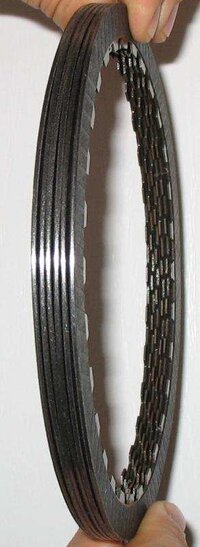
When I took it apart yesterday, the B and F clutch friction plates were warped (up to 0.7 mm gaps between plates in B clutch), the steels, however, were flat with no indication of damage or burning.
IMG_3196.jpg
Apart from that I really could not find any indication of the problem. I did not open the valve body since the truck was driving fine before and it was an obvious problem with the reverse gear in the first place (snap ring, flat spring, and the piston).
I really appreciate any advice that you may have for me.
Thanks a lot.
 
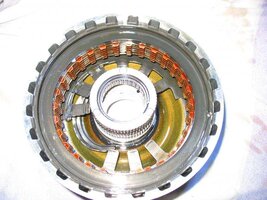
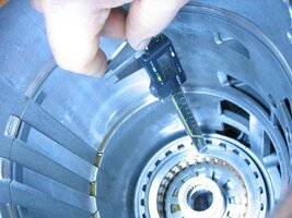
You clearly have one (or more) clutches dragging which could either be caused by a mechanical issue or a hydraulic one. You need to ensure that the clutch clearances are all to spec. to confirm that you've rebuilt each of them correctly. You can see typical figures in the example below :

ClutchPlateThicknesses.jpg


ClutchPlateClearances.jpg


An important point to note is that the rebuild kit will come with 5 plates for the 'D' clutch/brake (specifically for the BMW X5 4.6i) but the Range Rover only uses 4 plates – you should have one left over!

I was recently helping a chap in New Zealand on another forum who had a similar problem to yours and it turned out that he'd rebuilt his A clutch incorrectly : http://rangerovers.net/forum/viewtopic.php?f=2&t=41009&start=30#p321827
 
Last edited by a moderator:
Thanks a lot, Bemble!
I will go and check my clutches, although I am pretty sure none of them was tight when I assembled them. I did not measure the clearance but did a "feel" test by grasping the plates with fingers and lifting them up in an assembled pack – all had clearance around 2 mm (the plates were pre-soaked in transmission fluid overnight). I have measured thickness of new friction plates and they were very close to those that I had replaced. I did not change any of the steels so I figured out the clearances would be very similar to the original once. May distortion on the friction plates cause the drag? Is it normal for new plates to be out of flat or this is something that happened as the result of the test drive? The test drive was short – about 10-15 minutes, and I did not drive the car after. IMG_3200.jpgBTW, my car is BMW X5, 4.4, 2001 .
 
Hi Bemble,
I thought it would be interesting for you to find out what the problem with my transmission was and what the end of the whole story is.
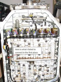
So I pulled it out the second time because of dragging in neutral and going forward in reverse. I became noticeably better at it. This time it took "only" four hours including jacking the truck on my driveway to create the 25' clearance required for the tranny to go through. I moved the transmission into the garage and disassembled everything again trying to find the error. All seals looked fine and nothing was wrong with the friction plates or steels. The clearances were: clutch A – 1.83mm, B – 1.96mm, C - 1.09mm, D – 1.60mm, E - 1.84mm, F - 3.04mm. Having a couple of clutches with lower than minimal clearance (thank you for the information in your previous message) got snap rings - Sx on your diagram - ground on a surface grinder to bring the clearance close to the nominal allowed and carefully put everything back together with a burden of uneasy feeling that the main problem had not been found yet. Checked the action of all the clutch packs with compressed air - each individually and using an adaptor plate after they were assembled in the transmission housing. Everything was happily clicking in and out … just like the first time. Well, having nothing else to check all was left to install the control unit. Only when aligning the valve body mounting holes I "noticed" under the wiring cable a little grey shaft with the fork-like bracket – something that I had missed altogether in the first time. Starting boiling from inside I have tweaked the bracket and the detent disk and they happily engaged with each other, so natural. My first thought was: No it can't be so simple and so …stupid. And, yet, it was. Finally I just sat back and laughed. You welcome to laugh with me at the amateur mistake – I really did all this transmission work first time in my life. Good news for me and my family (anxiously waiting for the truck to be back on the road) were that the vehicle would be fine now …and it was. The thought that I even did not have to pull the transmission out this time if I knew what the problem was (it would be just a matter of dropping the oil pan) did not bother me a lot as long as the transmission is fixed and we can use the vehicle again. Another 7 hours to install the transmission (that day happened to be windy and snowy) and assemble all of the pipes, shafts, clips, plugs, trims, etc. and the truck was ready for the test drive. Nice drive, smooth shifting, no vibration, and as I can see it now after three days of driving – improved fuel consumption.
Thanks everyone who helped me in this project with parts, manual, specifications, or just friendly advice: Bemble from Land Rover UK forum; Eriksson Industries [mailto:[email protected]]; Europeantransmissions and Parts [email protected]; local pros Brian, David, and George, and Swissfrankin particular, who's post on Xoutpost.com - X5 (E53) Forum inspired me to tackle the job in the first place.
Here are some pictures:
IMG_3017.jpgIMG_3205.jpgNew Picture.jpg5HP24.jpgIMG_3203.jpgIMG_3225.jpg
 
Last edited by a moderator:
Thanks for finishing off the story and I'm glad you're all sorted out now. The 'little grey shaft with the fork-like bracket' is the manual selector valve which provides reverse, neutral and drive modes in the event of the electronics failing (limp-home). The inhibitor switch would have been telling the ECU that you'd moved the selector lever to 'R' for it to engage the C & F clutches but the manual selector valve would have been engaging the A clutch to drive forwards. An interesting combination, as you found out!

With the benefit of hindsight I should have pointed you towards this post I'd made over on RangeRovers.net :
http://rangerovers.net/forum/viewtopic.php?f=2&t=34392&start=15#p298057

Anyway, good to hear that you're back on the road again.
 
Last edited by a moderator:
Hi Bemble,
I see your job, good job. I Have 5hp24 too and I search one copy to manual repair because I move my valve ( valve white, blue, black ...) and I m not sur to exactly place.
can you help me?
best regards.
 
Hi pierre,

Yes I'll be happy to help if I can.

I'm guessing English isn't your first language and I'm a little confused by your question. Could you maybe post up a photograph of the valves that you're referring to, to help my understanding?
 
thank you for you help Bemble. yes i am frenchi!
I have rebuilt my gearbox 5hp24 to jaguar xjv8 1999. always same problem, the input shaft broken.
I to do photo of my problem, see after:
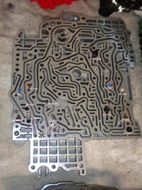
emplacement valve.jpg
I have 8 valves color for 9 emplacemnt. I think to do a mix.
have you a photo or picture to real position valves, please?
 
Pierre,

Now I understand!

All the orifice valve positions in your duct plate are correct in the photograph (3 x brown, 2 x blue, 2 x white & 1 x black, all in the correct places). Why do you think that there should be nine rather than eight?
 
Back
Top Bottom