Just over a year ago I was looking very seriously at upgrading the suspension setup on my Land Rover Defender 90. Over the year to come I planned to use the vehicle for a series of overland trips, green laning, towing, hauling gear and as my daily commute to work. So whatever I would eventually end up installing would have to be "all things to all men", a load-lugger, extremely competent off road, extremely competent on road, rugged and repaired by anyone (including myself) should the need arise.
Up until that point I had previously replaced the Land Rover standard springs and shocks with a series of setups and additional suspension extras (in approximate order)
After making a significant wish list of the systems on offer it boiled down to two; the Gwyn Lewis Challenge Kit and QT Services Weekender Kit. The other kits were removed from the list due to, cost, complexity and parts used. Both the GW and QT kits are simple bolt on and use kits that are not meant to change the on road manners of the vehicle, whilst affording it with excellent off road ability. My eventual choice came down to the utter simplicity of the kit, cost and being fairly local to the manufacturer, and designer, of the kit.
What follows is a description of the Gwyn Lewis Challenge Kit and the steps I took to remove the old suspension and fit the Gwyn Lewis Challenge Kit.
The Challenge Kit
Gwyn has spent many years designing and refining his suspension kits whilst trialling them in his own vehicles and has gone on to considerable success in the off road competition scene. Each part has been designed to improve on the coil sprung Land Rovers already legendary ability with parts that fit directly in to the standard position and with negligible modification of any body or chassis parts. Every part in the kit is dip galvanized to prolong the life and ward off the evil Tin-worm.
Some of the features of this kit include:
Included in the kit I bought are:
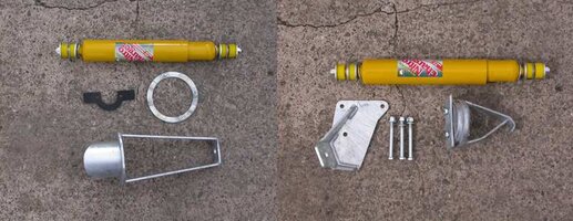
I decided on the Old Man Emu (OME) shocks over the other available shock (Rough Country) because of their tried and tested ruggedness that is trusted throughout the 4x4 world. Since I was planning to be carrying significant weights over long distances and rough terrains I was willing to spend the extra the OME shocks cost for the security of knowledge that they were more than up to the task.
WARNING: If you do not already have them fitted it is highly recommended that you buy a set of extended brake hoses as well.
Fitting The Kit
The tools I used are listed below, these are by no means exactly what you need to the job as you can supplement items for equivalent items, the Hi-lift jack for axle stands for example. Of course if you have access to such things as vehicle lifts and air tools then use them where applicable.
Tools Required
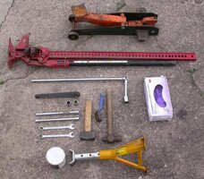
Before starting spray every nut with penetrating oil or equivalent, several applications over a number of days is a good idea.
The Rear Suspension
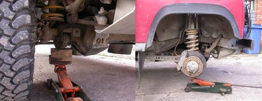
Chock wheels and remove one of the rear wheels
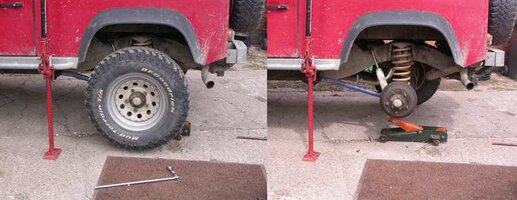
Support vehicle on axle stands and/or Hi-lift jack. Place axle stands place under the chassis rails as you are going to need to use the garage jack to raise the axle end up and down. Make sure the vehicle is secure as you are going to be working in, around and partially under it. Be Careful!
Removing the rear shock absorber
Using both an 8 mm and 17 mm spanner remove the bottom nut holding the shock to the axle. If the 8 mm spanner begins to slip on the stub end of the shock try pulling back on the lower shock body whilst turning the nut. It is NOT advisable to use heat on shocks, they are pressurized and may explode.
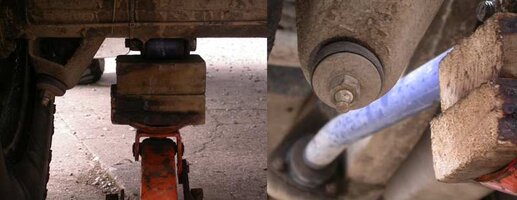
Using a 19 mm socket and ratchet remove the upper mounting nut of the shock.
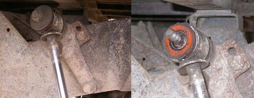
Remove shock by pulling the top off the upper mount and pulling out of the lower mount on the axle.
Removing the upper shock mount
There are three nuts and bolts attaching this mount to the chassis, they go all the way through the chassis. These will be replaced with new ones supplied with the kit.
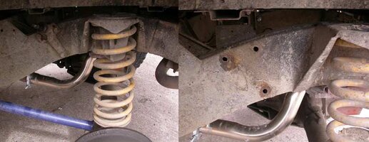
Using a 17 mm open ended spanner and a 17 mm socket and ratchet remove the three nuts and bolts.
If these are stubborn try bracing the spanner against the mount body whilst using the breaker bar and 17 mm socket to loosen the nuts. If this fails use more penetrating oil and try again later. You shouldn't have to resort to heat or angle grinders here.
Remove bolts and upper shock mount.
Removing rear spring
WARNING: before you do this next process to make sure the vehicle is secure with axle stands holding the weight of the chassis and body at the corner you are working on.
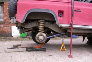
This is a personal preference, I prefer not to use spring compressors as I consider them to be ridiculously dangerous tools. Instead with the vehicle held on axle stands (and or Hi-lift jack) the spring can be removed easily by lowering the end of the axle on the garage jack. If you are at all worried or concerned about doing this then take it to a garage so they can do the suspension swap for you.
With the axle raised and the spring located in the upper chassis mount.
Without dislocation cones
Using a 17 mm socket on two long extensions bars and a ratchet remove the two bolts holding the lower spring retaining bar in place. Lower the socket and extension bars down through the top of the chassis mount.
With dislocation cones
Using the ring end of a 17 mm open ended spanner undo the spring retaining bar bolts by sliding the spanner through the bottom rings of the spring.
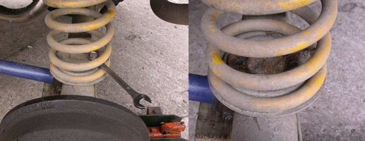
These bolts can be a difficult to remove as they thread down in to captive nuts under the axle mounting, make sure you use plenty of penetrating oil on these prior to trying to undoing them. It may be necessary to use heat to free these up. Once the bolts are out remove the retaining bar.
It is not unusual for one or two of these bolts to shear off, in which case the remaining stud will have to be removed, the hole drilled out and re-tapped.
Once the retaining bar has been removed there is nothing holding the spring to the vehicle. Lower the garage jack slowly, so lowering the axle end. The spring will slowly decompress and eventually drop out of the chassis mount where it can be removed, along with the axle mounting plate.
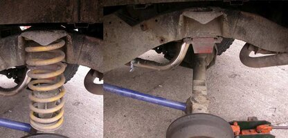
In the bottom of the spring is a dislocation cone.
Everything is now off that needs to be. Take your time and using the wire brush clean up the parts removed you will be using again and the axle and chassis mounting areas. If you has a bolt shear sort it out now.
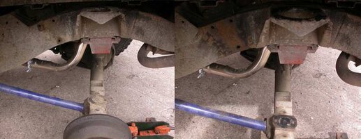
After cleaning up the mating surfaces with a wire brush it is a good idea to smear a layer of copper grease over them, you can of course use a chassis preservative such as Waxoyl instead.
Installing upper shock mount
The bits: upper shock mount, 3x bolts, 6x washers and 3x nylock nuts. Also a 17 mm open ended spanner and 17 mm socket and ratchet.
The key words with installing anything on to a vehicle is "grease it up and tighten it up well", so copper grease all the bolts, nuts and mating surfaces. Slot the bolts through the shock mount holes (making sure there is a washer between them) and then through the chassis mounting holes (it will only fit one way). Reaching under the chassis member, place a washer on each bolt and then a nylock nut. Tighten up well.
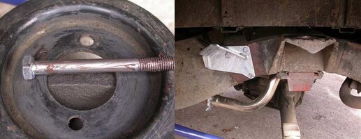
Installing dislocation cone
The dislocation cone is installed before the spring.
The bits needed: 1x dislocation cone, 1x bracing bar, 2x bolts and 2x nylock nuts.
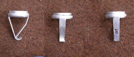
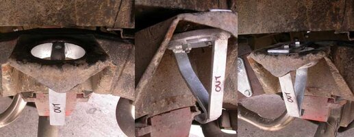
The Challenge cones will only fit one way and it is important that the instructions are followed. The dislocation cone is asymmetric with a hook at the lowest point. When being installed the hook should face the chassis member (away from you), there should be the word "OUT" written on the strut of the cone and facing you.
When offered up in to the chassis spring mount it will be obviously slightly smaller than the hole in the centre of the spring mount, this is intentional. Looking under the mount, the mating surface for the dislocation cone undulates, it is necessary to bend two of the points in to the centre of the hole. There are only two that can be easily got at.
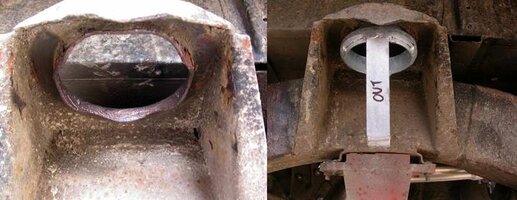
Using a lump hammer and a ball pin hammer (cole chisel or other handy implement), place the ball of the hammer on to one of the points and hit the face of the hammer with the lump hammer. This will bend the points inwards toward the centre of the hole; continue until the dislocation cone when offered up in the hole doesn't fall out.
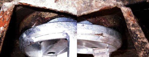
Grease the 2 bolts and Nylock nuts, fit the flat brace across the top of the chassis mount and slot the bolts down through the dislocation cone. Fit the nuts and tighten up using a 17 mm open ended spanner, 17 mm socket and ratchet.
Fitting the shock absorber
The bits needed: 1x shock absorber, 2x sets of bushes and plates and 2x nylock nuts.
Before installation of the shock it is important to prime it; do this by extending it to its maximum and then compressing it again. Do this a number of times before fitment.
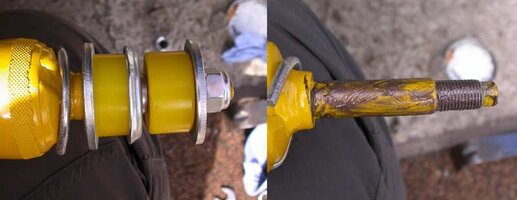
It is very important to get the order of the bushes and plates correct, see below diagram for the correct way. This is the same for both ends of the shock absorber.
Grease all mating surfaces and threads.
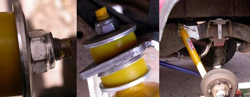
Over the greased end of the shock slide the first three pieces of the bush assembly; Plate 1, Bush 1 and then Plate 2 (making sure the raised ridge is pointing towards the thread). The raised portion of Plate 2 is designed to slot in to the hole of the shock mounting bracket, make sure when installing that it is flat against the mounting bracket.
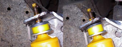
Install the shock in to the chassis mount first. Slide Bush 2 and Plate 3 down over the protruding thread and screw on one of the Nylock nuts by finger.
Install the shock in to the axle mounting bracket and add Bush 2, Plate 3 and the Nylock nut on to the threaded end.
When both of the Plate 2 washers are located correctly in to the holes of the mounting bracket take a 17 mm open ended spanner and tighten the nuts. Tighten the nuts until 2 thread ridges appear above the top of the nut.
Installing the spring
The bits needed: 1x spring, 1x lower mounting plate, retaining bar, 2x bolts and 2x washers. NB: If you had to drill out the bolts earlier you may need to use nuts under the axle mount instead of the captive nuts.
Take the spring and insert it up in to the chassis mount and over the axle mounting. Slide the lower mounting plate under the spring and align the holes with the axle mounting.
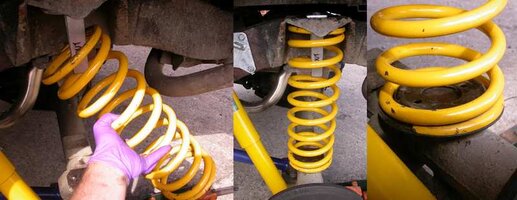
Slide the spring retaining bar over the lowermost spring ring and align with the 2 holes in the mounting plate. Drop a bolt with washer in to each of the holes and turn with fingers to find the thread of the captive nut. Do not cross thread!
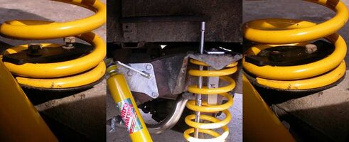
Using a 17 mm socket, 2 long extensions and a ratchet; lower down through the top of the chassis mounting and tighten the 2 lower mounting plate bolts.
That is one side of the rear done.
Here are some photos of the rear end complete, how the dislocation cones silently re-locate the springs and the use of the dislocation cones to limit the axle droop for the purposes of changing a wheel.
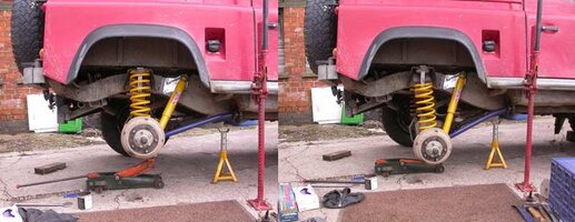
Rear fitted, before and after
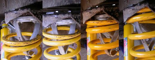
Relocation of rear spring
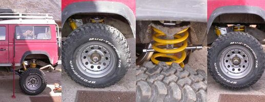
Use of dislocation cone when changing a wheel
The Front Suspension
With the rear suspension replaced all that needs to be done is the front end, which is just as straight forward with just the smallest modification within the engine bay, I mean really small!!
Tools Required
The tools required are predominately the same as for replacing the rear suspension with the exception of:
2 x 10 mm open ended spanners (or a 10 mm socket in place of one of the spanners).
1 x 8 mm open ended spanner
1 x cross-head screwdriver
1 x 13 mm socket
1 x Small round file
Dismantling the front shock absorber assembly
The night before: To gain access to the top of the shocks securely prop the bonnet up. Looking in to the engine bay from the front of the vehicle there are two black plastic covers situated on the top of the wheel arches. These are held in place by 6 cross-head screws. The cover on the near side of the engine bay is easy to get to, the opposite cover requires the radiator expansion tank to be moved out of the way first.
Moving the radiator expansion tank: Using 2 x 10 mm open ended spanners, undo the two bolts attaching the tank to the wing (NB. they are NOT captive so get ready to catch them!) and push the expansion tank towards the engine on the lower supporting strap.
NB: You DO NOT need to empty the coolant system.
The screws holding the plastic cap on can now be accessed, unscrewed and the cap removed. Under the cap is the top of the shock absorber turret and the nut holding the shock in place. Spray plenty of penetrating oil on to every nut and bolt, and leave overnight.
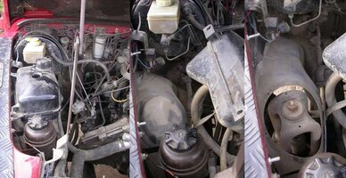
The day after: Chock wheels and remove one of the front wheels. Support vehicle on axle stands and/or Hi-lift jack. Place axle stands place under the chassis rails as you are going to need to use the garage jack to raise the axle end up and down.
Make sure the vehicle is secure as you are going to be working in, around and partially under it. Be Careful!
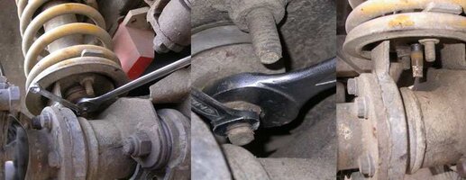
Using an 8 mm and 17 mm open ended spanner remove the bottom nut of the shock absorber. Give the nut another spray of penetrating oil. The threaded stud of the shock has two flattened edges which the 8 mm spanner can be slotted on too, then using the 17 mm spanner undo the nut. There is not much space under the bottom mount to get the spanners in and even less space to turn them. Do not "beast" this as the flattened edges of the shock stud are easily rounded off, if this happens a mole wrench can be used to lock on to the bottom of the shock stud whilst the nut is turned slowly. Use plenty of penetrating oil.
Removing the shock turret
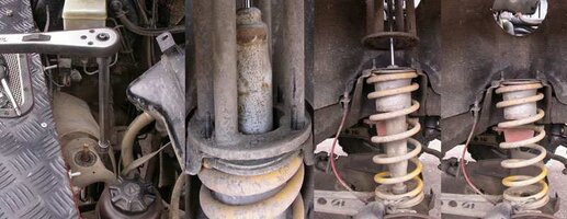
Using a 13 mm socket, 2 x long extension bars and a ratchet remove the nuts holding the turret in place, do this by lowering the socket and bars down through the hole in the wheel arch. Once the 4 nuts have been removed the turret will rise up as the shock absorber extends to its full length. Remove the turret and shock up through the wheel arch and engine bay.
Removing the spring
This is not strictly necessary if you are happy with the state of the turret retaining ring and are not replacing the springs, however because I had to remove the existing dislocation cone the spring had to come out.
Remove the spring retaining bar if you have one fitted, these were not fitted as standard, however you will still need to remove the bolts holding the bottom spring mount to the axle in order to fit the new retaining bar. Using a 17 mm socket, extension bars and ratchet, undo the bolts by lowering the tools down through the top chassis spring mount.
With the bar removed there is nothing holding the spring in place. Using the same method as the rear for removing the spring;
WARNING: before you do this next process to make sure the vehicle is secure with axle stands holding the weight of the chassis and body at the corner you are working on.
This is a personal preference, I prefer not to use spring compressors as I consider them to be ridiculously dangerous tools. Instead with the vehicle held on axle stands (and or Hi-lift jack) the spring can be removed easily by lowering the end of the axle on the garage jack. If you are at all worried or concerned about doing this then take it to a garage so they can do the suspension swap for you.
With the axle raised and the spring located in the upper chassis mount. Lower the garage jack slowly, so lowering the axle end. The spring will slowly decompress and eventually drop out of the chassis mount where it can be removed, along with the axle mounting plate.
Everything is now off that needs to be. Take your time and using the wire brush clean up the parts removed you will be using again and the axle and chassis mounting areas. After cleaning up the mating surfaces with a wire brush it is a good idea to smear a layer of copper grease over them, you can of course use a chassis preservative such as Waxoyl instead.
Fitting the spring
Before replacing the spring back in to the vehicle, copper grease the new turret retaining ring and install it in to the chassis spring mount, from the underside of the mount. To temporarily fix the retaining ring in place loosely screw a couple of nuts on to the studs sticking through the chassis mount.
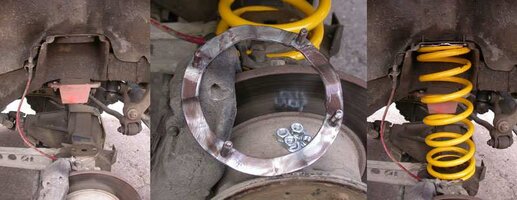
With the axle still in the lowered position replace the spring and lower spring mounting plate. Using the garage jack raise the axle upwards until it is held in place by the chassis mount. Make sure that the holes for fixing the axle mounting plate are aligned.
Slide the spring retaining bar over the lowermost spring ring and align with the 2 holes in the mounting plate. Drop a bolt with washer in to each of the holes and turn with fingers to find the thread of the captive nut. Do not cross thread! Using a 17 mm socket, 2 long extensions and a ratchet; lower down through the top of the chassis mounting and tighten the 2 lower mounting plate bolts.
Fitting the shock absorber in to the shock turret
Unlike the rear shock installation, the front shock is best installed in to the shock turret before either of them are fitted in to the vehicle. The Challenge kit turrets are different to standard shock turrets as they are raised and asymmetrical, they also have an integral dislocation cone.
NB: the turrets are labelled to assist in installation, however should they not be and because they are "sided" the easiest way to identify which turret is which is by the "lean" of the turret; the turret should lean backwards.
The bits needed; 1 x shock absorber, 1 x shock absorber turret, 2 x sets of bushes and plates and 2 x nylock nuts.
Before installation of the shock it is important to prime it; do this by extending it to its maximum and then compressing it again. Do this a number of times before fitment.
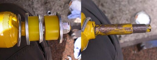
It is very important to get the order of the bushes and plates correct, see below diagram for the correct way. This is the same for both ends of the shock absorber.
Grease all mating surfaces and threads.
Over the greased end of the shock slide the first three pieces of the bush assembly; Plate 1, Bush 1 and then Plate 2 (making sure the raised ridge is pointing towards the thread). The raised portion of Plate 2 is designed to slot in to the hole of the shock turret, make sure when installing that it is flat against the underside of the mounting surface. Slide Bush 2 and Plate 3 down over the protruding thread and screw on one of the Nylock nut by finger.
When both of the Plate 2 washers are located correctly in to the hole of the shock turret, take a 17 mm and 8 mm open ended spanner and tighten the nut. Tighten the nut until 2 thread ridges appear above the top of the nut.
Remove the nuts from the turret retaining ring.
Lower the shock and turret assembly down through the top of the wheel arch, in the engine bay. Make sure that the turret is the correct way around.
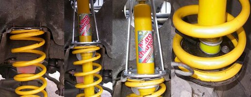
Add on to the lower threaded stud of the shock absorber Plate 1, Bush 1 and then Plate 2, making sure the raised ridge of Plate 2 is pointing towards the thread. Locate the lower shock absorber threaded stud in to the hole in the centre of the lower axle plate.
Pushing down on the top of the shock, locate the shock turret on to the 4 protruding studs of the retaining ring and screw the washers and nuts on to the studs by hand. Using a 13 mm socket, extension bars and ratchet, tighten the nuts.
On to the underneath of the lower shock threaded stud slide Bush 2 and Plate 3 over the protruding thread and screw on one of the Nylock nut by finger. Take a 17 mm and 8 mm open ended spanner and tighten the nut, tighten until 2 thread ridges appear above the top of the nut.
Once this has been done on both sides of the vehicle he suspension change is almost complete.
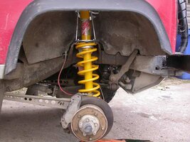
Due to the shock turrets being taller than the standard items the black plastic covers that were taken off the inner wheel arch are now redundant.
Replacing the radiator expansion tank
Due to the shock turrets being a little taller the expansion tank needs to be raised and shifted backwards a little to accommodate it. In total the tank needs to be raised about 1 cm and back about 2 cm, just enough to clear the top of the shock absorbers threaded stud. Using a small round file, file out the two holes on either side of the tank, they are plastic so it is easily done.
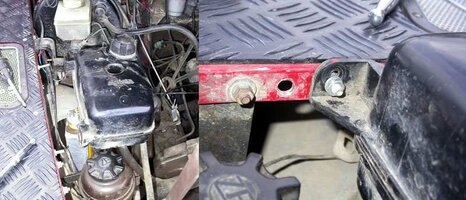
Using 2 x 13 mm open ended spanners, remove the lower stabilizing bar off the inner wheel arch.
With the tank free line it up on the edge of the wing and mark where the holes are, drill holes in edge.
Using 2 x 10 mm open ended spanners replace the tank on to the wing, in its new position, using the original nuts and bolts.
Pressing the retaining strap up against the wheel arch mark the position of the hole. Drill out the wheel arch and fix the strap in place using the nut and bolt.
Well that is it, all done! Go out and enjoy your vehicles new capabilities, but take it easy to start with until you have become accustomed to how the new setup behaves, both on and off road.
Here are some photos of the completed suspension change and what it can do, there are before (with standard +2" lift kit) and after shots (with the Challenge Kit).
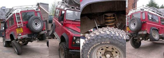
Before

After 1
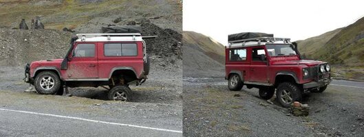
After 2
Questions
If you have any questions please don't hesitate to ask. You can also find out more information from Gwyn on his website or give him a bell on – 01938 810298 or at www.gwynlewis4x4.co.uk
Up until that point I had previously replaced the Land Rover standard springs and shocks with a series of setups and additional suspension extras (in approximate order)
- Bearmach +2" springs and Monroe +2" 4x4 Adventurer shocks,
- Upgraded to ProComp +2" shocks and +2" brake hoses as the shocks allowed for greater droop. Secured rear springs in to upper mounts with exhaust clamps to prevent dislocaton,
- Replaced front radius arms with QT castor corrected arms to return the geometry of the front suspension, steering and pinion angles back to standard and re-bushed the vehicle with Blue PolyBushes,
- Replaced the exhaust clamps with dislocation cones, upgraded the front and rear spring retaining bars (hold spring on to axle), replaced front turrets with standard height galvanized tubular versions, heavier duty turret retaining rings and front dislocation cones.
- Replaced sagging Bearmach springs with new set of the same,
- Replaced Bearmach springs with +2" Britpart heavier duty yellow springs as the Bearmachs felt awful. At the same time replaced lost standard bump stops with +2" versions,
- Replaced rear traillng arms with Gwyn Lewis cranked trailing arms and replaced worn Polybushes with Bearmach versions.
After making a significant wish list of the systems on offer it boiled down to two; the Gwyn Lewis Challenge Kit and QT Services Weekender Kit. The other kits were removed from the list due to, cost, complexity and parts used. Both the GW and QT kits are simple bolt on and use kits that are not meant to change the on road manners of the vehicle, whilst affording it with excellent off road ability. My eventual choice came down to the utter simplicity of the kit, cost and being fairly local to the manufacturer, and designer, of the kit.
What follows is a description of the Gwyn Lewis Challenge Kit and the steps I took to remove the old suspension and fit the Gwyn Lewis Challenge Kit.
The Challenge Kit
Gwyn has spent many years designing and refining his suspension kits whilst trialling them in his own vehicles and has gone on to considerable success in the off road competition scene. Each part has been designed to improve on the coil sprung Land Rovers already legendary ability with parts that fit directly in to the standard position and with negligible modification of any body or chassis parts. Every part in the kit is dip galvanized to prolong the life and ward off the evil Tin-worm.
Some of the features of this kit include:
- an asymmetric front shock turret design that allows the axle to droop further without the body of the shock fouling on the chassis spring mount,
- an open shock turret design to aid in cleaning and servicing,
- an integrated front dislocation cone in to the front turret to retain the spring and prevent it from impacting on the front shock,
- taller front shock turrets to accommodate the longer shocks,
- a realigned rear upper shock mount to allow for the longer shocks whilst maintaining both the upwards and downwards axle movement,
- an asymmetrical rear dislocation cone that relocates the spring smoothly and quietly in to the chassis mount
- hooks on the end of the rear dislocation cones catch on to the last ring of the springs to prevent them from going beyond the cone. The hook also doubles as a means of limiting the axle movement, with the aid of a wheel brace, whilst changing a wheel.
Included in the kit I bought are:
- Rear: Old Man Emu Shocks, rear dislocation cones and rear upper shock mounts
- Front: Old Man Emu Shocks, integrated front turret and dislocation cones and turret retaining ring.

I decided on the Old Man Emu (OME) shocks over the other available shock (Rough Country) because of their tried and tested ruggedness that is trusted throughout the 4x4 world. Since I was planning to be carrying significant weights over long distances and rough terrains I was willing to spend the extra the OME shocks cost for the security of knowledge that they were more than up to the task.
WARNING: If you do not already have them fitted it is highly recommended that you buy a set of extended brake hoses as well.
Fitting The Kit
The tools I used are listed below, these are by no means exactly what you need to the job as you can supplement items for equivalent items, the Hi-lift jack for axle stands for example. Of course if you have access to such things as vehicle lifts and air tools then use them where applicable.
Tools Required
- Hi-lift jack
- Garage jack
- ½" ratchet
- 17 mm socket
- 19 mm socket
- ½" breaker bar
- 2 x 17 mm open ended spanner
- Lump hammer
- Wire brush
- 8 mm open ended spanner
- Copper grease
- Axle stands
- Wheel brace or 27 mm socket
- Wheel chocks
- Latex gloves
- Ball-pin hammer or Cole Chisel

Before starting spray every nut with penetrating oil or equivalent, several applications over a number of days is a good idea.
The Rear Suspension
Chock wheels and remove one of the rear wheels

Support vehicle on axle stands and/or Hi-lift jack. Place axle stands place under the chassis rails as you are going to need to use the garage jack to raise the axle end up and down. Make sure the vehicle is secure as you are going to be working in, around and partially under it. Be Careful!
Removing the rear shock absorber
Using both an 8 mm and 17 mm spanner remove the bottom nut holding the shock to the axle. If the 8 mm spanner begins to slip on the stub end of the shock try pulling back on the lower shock body whilst turning the nut. It is NOT advisable to use heat on shocks, they are pressurized and may explode.

Using a 19 mm socket and ratchet remove the upper mounting nut of the shock.

Remove shock by pulling the top off the upper mount and pulling out of the lower mount on the axle.
Removing the upper shock mount
There are three nuts and bolts attaching this mount to the chassis, they go all the way through the chassis. These will be replaced with new ones supplied with the kit.

Using a 17 mm open ended spanner and a 17 mm socket and ratchet remove the three nuts and bolts.
If these are stubborn try bracing the spanner against the mount body whilst using the breaker bar and 17 mm socket to loosen the nuts. If this fails use more penetrating oil and try again later. You shouldn't have to resort to heat or angle grinders here.
Remove bolts and upper shock mount.
Removing rear spring
WARNING: before you do this next process to make sure the vehicle is secure with axle stands holding the weight of the chassis and body at the corner you are working on.

This is a personal preference, I prefer not to use spring compressors as I consider them to be ridiculously dangerous tools. Instead with the vehicle held on axle stands (and or Hi-lift jack) the spring can be removed easily by lowering the end of the axle on the garage jack. If you are at all worried or concerned about doing this then take it to a garage so they can do the suspension swap for you.
With the axle raised and the spring located in the upper chassis mount.
Without dislocation cones
Using a 17 mm socket on two long extensions bars and a ratchet remove the two bolts holding the lower spring retaining bar in place. Lower the socket and extension bars down through the top of the chassis mount.
With dislocation cones
Using the ring end of a 17 mm open ended spanner undo the spring retaining bar bolts by sliding the spanner through the bottom rings of the spring.

These bolts can be a difficult to remove as they thread down in to captive nuts under the axle mounting, make sure you use plenty of penetrating oil on these prior to trying to undoing them. It may be necessary to use heat to free these up. Once the bolts are out remove the retaining bar.
It is not unusual for one or two of these bolts to shear off, in which case the remaining stud will have to be removed, the hole drilled out and re-tapped.
Once the retaining bar has been removed there is nothing holding the spring to the vehicle. Lower the garage jack slowly, so lowering the axle end. The spring will slowly decompress and eventually drop out of the chassis mount where it can be removed, along with the axle mounting plate.

In the bottom of the spring is a dislocation cone.
Everything is now off that needs to be. Take your time and using the wire brush clean up the parts removed you will be using again and the axle and chassis mounting areas. If you has a bolt shear sort it out now.

After cleaning up the mating surfaces with a wire brush it is a good idea to smear a layer of copper grease over them, you can of course use a chassis preservative such as Waxoyl instead.
Installing upper shock mount
The bits: upper shock mount, 3x bolts, 6x washers and 3x nylock nuts. Also a 17 mm open ended spanner and 17 mm socket and ratchet.
The key words with installing anything on to a vehicle is "grease it up and tighten it up well", so copper grease all the bolts, nuts and mating surfaces. Slot the bolts through the shock mount holes (making sure there is a washer between them) and then through the chassis mounting holes (it will only fit one way). Reaching under the chassis member, place a washer on each bolt and then a nylock nut. Tighten up well.

Installing dislocation cone
The dislocation cone is installed before the spring.
The bits needed: 1x dislocation cone, 1x bracing bar, 2x bolts and 2x nylock nuts.

The Challenge cones will only fit one way and it is important that the instructions are followed. The dislocation cone is asymmetric with a hook at the lowest point. When being installed the hook should face the chassis member (away from you), there should be the word "OUT" written on the strut of the cone and facing you.
When offered up in to the chassis spring mount it will be obviously slightly smaller than the hole in the centre of the spring mount, this is intentional. Looking under the mount, the mating surface for the dislocation cone undulates, it is necessary to bend two of the points in to the centre of the hole. There are only two that can be easily got at.

Using a lump hammer and a ball pin hammer (cole chisel or other handy implement), place the ball of the hammer on to one of the points and hit the face of the hammer with the lump hammer. This will bend the points inwards toward the centre of the hole; continue until the dislocation cone when offered up in the hole doesn't fall out.

Grease the 2 bolts and Nylock nuts, fit the flat brace across the top of the chassis mount and slot the bolts down through the dislocation cone. Fit the nuts and tighten up using a 17 mm open ended spanner, 17 mm socket and ratchet.

Fitting the shock absorber
The bits needed: 1x shock absorber, 2x sets of bushes and plates and 2x nylock nuts.
Before installation of the shock it is important to prime it; do this by extending it to its maximum and then compressing it again. Do this a number of times before fitment.
It is very important to get the order of the bushes and plates correct, see below diagram for the correct way. This is the same for both ends of the shock absorber.

Grease all mating surfaces and threads.
Over the greased end of the shock slide the first three pieces of the bush assembly; Plate 1, Bush 1 and then Plate 2 (making sure the raised ridge is pointing towards the thread). The raised portion of Plate 2 is designed to slot in to the hole of the shock mounting bracket, make sure when installing that it is flat against the mounting bracket.

Install the shock in to the chassis mount first. Slide Bush 2 and Plate 3 down over the protruding thread and screw on one of the Nylock nuts by finger.
Install the shock in to the axle mounting bracket and add Bush 2, Plate 3 and the Nylock nut on to the threaded end.
When both of the Plate 2 washers are located correctly in to the holes of the mounting bracket take a 17 mm open ended spanner and tighten the nuts. Tighten the nuts until 2 thread ridges appear above the top of the nut.

Installing the spring
The bits needed: 1x spring, 1x lower mounting plate, retaining bar, 2x bolts and 2x washers. NB: If you had to drill out the bolts earlier you may need to use nuts under the axle mount instead of the captive nuts.
Take the spring and insert it up in to the chassis mount and over the axle mounting. Slide the lower mounting plate under the spring and align the holes with the axle mounting.

Slide the spring retaining bar over the lowermost spring ring and align with the 2 holes in the mounting plate. Drop a bolt with washer in to each of the holes and turn with fingers to find the thread of the captive nut. Do not cross thread!

Using a 17 mm socket, 2 long extensions and a ratchet; lower down through the top of the chassis mounting and tighten the 2 lower mounting plate bolts.
That is one side of the rear done.
Here are some photos of the rear end complete, how the dislocation cones silently re-locate the springs and the use of the dislocation cones to limit the axle droop for the purposes of changing a wheel.

Rear fitted, before and after

Relocation of rear spring

Use of dislocation cone when changing a wheel
The Front Suspension
With the rear suspension replaced all that needs to be done is the front end, which is just as straight forward with just the smallest modification within the engine bay, I mean really small!!
Tools Required
The tools required are predominately the same as for replacing the rear suspension with the exception of:
2 x 10 mm open ended spanners (or a 10 mm socket in place of one of the spanners).
1 x 8 mm open ended spanner
1 x cross-head screwdriver
1 x 13 mm socket
1 x Small round file
Dismantling the front shock absorber assembly
The night before: To gain access to the top of the shocks securely prop the bonnet up. Looking in to the engine bay from the front of the vehicle there are two black plastic covers situated on the top of the wheel arches. These are held in place by 6 cross-head screws. The cover on the near side of the engine bay is easy to get to, the opposite cover requires the radiator expansion tank to be moved out of the way first.
Moving the radiator expansion tank: Using 2 x 10 mm open ended spanners, undo the two bolts attaching the tank to the wing (NB. they are NOT captive so get ready to catch them!) and push the expansion tank towards the engine on the lower supporting strap.
NB: You DO NOT need to empty the coolant system.
The screws holding the plastic cap on can now be accessed, unscrewed and the cap removed. Under the cap is the top of the shock absorber turret and the nut holding the shock in place. Spray plenty of penetrating oil on to every nut and bolt, and leave overnight.

The day after: Chock wheels and remove one of the front wheels. Support vehicle on axle stands and/or Hi-lift jack. Place axle stands place under the chassis rails as you are going to need to use the garage jack to raise the axle end up and down.
Make sure the vehicle is secure as you are going to be working in, around and partially under it. Be Careful!

Using an 8 mm and 17 mm open ended spanner remove the bottom nut of the shock absorber. Give the nut another spray of penetrating oil. The threaded stud of the shock has two flattened edges which the 8 mm spanner can be slotted on too, then using the 17 mm spanner undo the nut. There is not much space under the bottom mount to get the spanners in and even less space to turn them. Do not "beast" this as the flattened edges of the shock stud are easily rounded off, if this happens a mole wrench can be used to lock on to the bottom of the shock stud whilst the nut is turned slowly. Use plenty of penetrating oil.

Removing the shock turret
Using a 13 mm socket, 2 x long extension bars and a ratchet remove the nuts holding the turret in place, do this by lowering the socket and bars down through the hole in the wheel arch. Once the 4 nuts have been removed the turret will rise up as the shock absorber extends to its full length. Remove the turret and shock up through the wheel arch and engine bay.

Removing the spring
This is not strictly necessary if you are happy with the state of the turret retaining ring and are not replacing the springs, however because I had to remove the existing dislocation cone the spring had to come out.
Remove the spring retaining bar if you have one fitted, these were not fitted as standard, however you will still need to remove the bolts holding the bottom spring mount to the axle in order to fit the new retaining bar. Using a 17 mm socket, extension bars and ratchet, undo the bolts by lowering the tools down through the top chassis spring mount.
With the bar removed there is nothing holding the spring in place. Using the same method as the rear for removing the spring;
WARNING: before you do this next process to make sure the vehicle is secure with axle stands holding the weight of the chassis and body at the corner you are working on.
This is a personal preference, I prefer not to use spring compressors as I consider them to be ridiculously dangerous tools. Instead with the vehicle held on axle stands (and or Hi-lift jack) the spring can be removed easily by lowering the end of the axle on the garage jack. If you are at all worried or concerned about doing this then take it to a garage so they can do the suspension swap for you.
With the axle raised and the spring located in the upper chassis mount. Lower the garage jack slowly, so lowering the axle end. The spring will slowly decompress and eventually drop out of the chassis mount where it can be removed, along with the axle mounting plate.
Everything is now off that needs to be. Take your time and using the wire brush clean up the parts removed you will be using again and the axle and chassis mounting areas. After cleaning up the mating surfaces with a wire brush it is a good idea to smear a layer of copper grease over them, you can of course use a chassis preservative such as Waxoyl instead.
Fitting the spring
Before replacing the spring back in to the vehicle, copper grease the new turret retaining ring and install it in to the chassis spring mount, from the underside of the mount. To temporarily fix the retaining ring in place loosely screw a couple of nuts on to the studs sticking through the chassis mount.

With the axle still in the lowered position replace the spring and lower spring mounting plate. Using the garage jack raise the axle upwards until it is held in place by the chassis mount. Make sure that the holes for fixing the axle mounting plate are aligned.
Slide the spring retaining bar over the lowermost spring ring and align with the 2 holes in the mounting plate. Drop a bolt with washer in to each of the holes and turn with fingers to find the thread of the captive nut. Do not cross thread! Using a 17 mm socket, 2 long extensions and a ratchet; lower down through the top of the chassis mounting and tighten the 2 lower mounting plate bolts.
Fitting the shock absorber in to the shock turret
Unlike the rear shock installation, the front shock is best installed in to the shock turret before either of them are fitted in to the vehicle. The Challenge kit turrets are different to standard shock turrets as they are raised and asymmetrical, they also have an integral dislocation cone.
NB: the turrets are labelled to assist in installation, however should they not be and because they are "sided" the easiest way to identify which turret is which is by the "lean" of the turret; the turret should lean backwards.
The bits needed; 1 x shock absorber, 1 x shock absorber turret, 2 x sets of bushes and plates and 2 x nylock nuts.
Before installation of the shock it is important to prime it; do this by extending it to its maximum and then compressing it again. Do this a number of times before fitment.
It is very important to get the order of the bushes and plates correct, see below diagram for the correct way. This is the same for both ends of the shock absorber.

Grease all mating surfaces and threads.
Over the greased end of the shock slide the first three pieces of the bush assembly; Plate 1, Bush 1 and then Plate 2 (making sure the raised ridge is pointing towards the thread). The raised portion of Plate 2 is designed to slot in to the hole of the shock turret, make sure when installing that it is flat against the underside of the mounting surface. Slide Bush 2 and Plate 3 down over the protruding thread and screw on one of the Nylock nut by finger.
When both of the Plate 2 washers are located correctly in to the hole of the shock turret, take a 17 mm and 8 mm open ended spanner and tighten the nut. Tighten the nut until 2 thread ridges appear above the top of the nut.
Remove the nuts from the turret retaining ring.
Lower the shock and turret assembly down through the top of the wheel arch, in the engine bay. Make sure that the turret is the correct way around.

Add on to the lower threaded stud of the shock absorber Plate 1, Bush 1 and then Plate 2, making sure the raised ridge of Plate 2 is pointing towards the thread. Locate the lower shock absorber threaded stud in to the hole in the centre of the lower axle plate.
Pushing down on the top of the shock, locate the shock turret on to the 4 protruding studs of the retaining ring and screw the washers and nuts on to the studs by hand. Using a 13 mm socket, extension bars and ratchet, tighten the nuts.
On to the underneath of the lower shock threaded stud slide Bush 2 and Plate 3 over the protruding thread and screw on one of the Nylock nut by finger. Take a 17 mm and 8 mm open ended spanner and tighten the nut, tighten until 2 thread ridges appear above the top of the nut.
Once this has been done on both sides of the vehicle he suspension change is almost complete.

Due to the shock turrets being taller than the standard items the black plastic covers that were taken off the inner wheel arch are now redundant.
Replacing the radiator expansion tank
Due to the shock turrets being a little taller the expansion tank needs to be raised and shifted backwards a little to accommodate it. In total the tank needs to be raised about 1 cm and back about 2 cm, just enough to clear the top of the shock absorbers threaded stud. Using a small round file, file out the two holes on either side of the tank, they are plastic so it is easily done.

Using 2 x 13 mm open ended spanners, remove the lower stabilizing bar off the inner wheel arch.
With the tank free line it up on the edge of the wing and mark where the holes are, drill holes in edge.
Using 2 x 10 mm open ended spanners replace the tank on to the wing, in its new position, using the original nuts and bolts.
Pressing the retaining strap up against the wheel arch mark the position of the hole. Drill out the wheel arch and fix the strap in place using the nut and bolt.
Well that is it, all done! Go out and enjoy your vehicles new capabilities, but take it easy to start with until you have become accustomed to how the new setup behaves, both on and off road.
Here are some photos of the completed suspension change and what it can do, there are before (with standard +2" lift kit) and after shots (with the Challenge Kit).

Before

After 1

After 2
Questions
If you have any questions please don't hesitate to ask. You can also find out more information from Gwyn on his website or give him a bell on – 01938 810298 or at www.gwynlewis4x4.co.uk
